TP-6252 2/08
34 Section 3 Scheduled Maintenance
3.7 Air Intake Silencer/Cleaner
At the interval specified in the service schedule, clean
or
replace
the air intake filter. Clean the filter more
frequently if the generator set operates in dirty, dusty
conditions. Follow one of the procedures described
below.
Air Cleaner Service/Replacement
6EOD, 8/9/10/13/20/28/32EOZD,
4.5EFOD, and 6.5/7/9/11/17/17.5/23/27EFOZD
Models:
A dry-type air cleaner silences and filters the intake air.
The air intake silencer assembly connects to the intake
manifold via a flexible hose.
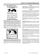
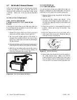
1. Release the spring clips to open the housing and
remove the air filter element. See Figure 3-6.
2. Tap the element lightly against a flat surface to
dislodge loose surface dirt. Do not clean in any
liquid or use compressed air as these will damage
the filter element.
3. Examine the element and housing for damage and
wear. Replace the element or housing if necessary.
4. Wipe the cover and base with a clean rag to remove
any dirt. Make sure that the sealing surfaces fit
correctly, and reattach the spring clips.
Figure 3-6
Air Cleaner Element Element
14/15.5/23/24EOZD and
11.5/13/20EFOZD Models:
A round air cleaner silences and filters the intake air.
Replace a damaged or dirt-contaminated air silencer.
See Section 1 and refer to the following procedure:
1. Release the two spring clips and remove the intake
silencer cover.
2. Remove the filter element and inspect. If the
element is not damaged, continue with step 3. If
the element is damaged, replace it, skip step 3, and
go to step 4.
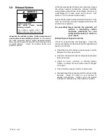
3. Wash the element in mild detergent and water
solution. Rinse and air dry the element. See
Figure 3-7.
4. Wipe the intake silencer cover and base with a
clean rag to remove any dirt. Check the base for
damage; replace as necessary.
1-776
1
1. Element
Figure 3-7
Element Washing
5. Reassemble the element and cover assembly to
the intake silencer base. Make sure that the
sealing surfaces fit and reattach the spring clips.
The air intake silencer duct should be at the 5
o’clock position as viewed from the generator end.
Содержание 4.5EFOD
Страница 1: ...Marine Generator Sets Models 6EOD 4 5EFOD 8 32EOZD 6 5 27EFOZD TP 6252 2 08c Operation ...
Страница 8: ...TP 6252 2 08 8 Safety Precautions and Instructions Notes ...
Страница 48: ...TP 6252 2 08 48 Section 5 Wiring Diagrams GM42202 E Figure 5 2 Wiring Diagram for Model 6EOD 4 5EFOD ...
Страница 49: ...TP 6252 2 08 49 Section 5 Wiring Diagrams ADV7095A D Figure 5 3 Schematic for Model 6EOD 4 5EFOD Sheet 1 of 2 ...
Страница 50: ...TP 6252 2 08 50 Section 5 Wiring Diagrams ADV7095B D Figure 5 4 Schematic for Model 6EOD 4 5EFOD Sheet 2 of 2 ...
Страница 51: ...TP 6252 2 08 51 Section 5 Wiring Diagrams GM50490 B Figure 5 5 Wiring Diagram for Model 9EOZD 7EFOZD ...
Страница 58: ...TP 6252 2 08 58 ...
Страница 59: ...TP 6252 2 08 59 ...

