TP-6252 2/08
43
Section 4 Troubleshooting
Section 4 Troubleshooting
This section contains generator set troubleshooting,
diagnostic, and repair information.
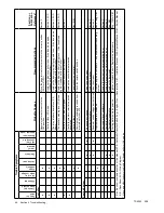
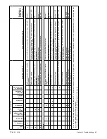
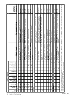
Use the following charts as a quick troubleshooting
reference. The table groups generator set faults and
suggests likely causes and remedies. The table also
refers you to more detailed information including
sections of this manual, the generator set service
manual (S/M), the generator set installation manual
(I/M), and the engine service manual (Engine S/M) to
correct the indicated problem.
Corrective action and testing often require knowledge of
electrical and electronic circuits. To avoid additional
problems caused by incorrect repairs, have an
authorized service distributor/dealer perform service.
NOTICE
Fuse replacement.
Replace fuses with fuses of the same
ampere rating and type (for example: 3AB or 314, ceramic).
Do not substitute clear glass-type fuses for ceramic fuses.
Refer to the wiring diagram when the ampere rating is
unknown or questionable.
Maintain a record of repairs and adjustments performed
on the equipment. If the procedures in this manual do
not explain how to correct the problem, contact an
authorized distributor/dealer. Use the record to help
describe the problem and repairs or adjustments made
to the equipment.
x:gt:001:002a:
4.1 Fault Codes
The Advanced Digital Control displays fault codes to aid
in troubleshooting. Fault codes, descriptions, and
recommended actions are listed in Figure 2-5.
Identify and correct the cause of the fault condition.
Then reset the controller after a fault shutdown. See
Section 2.6.5.
4.2 Controller Troubleshooting
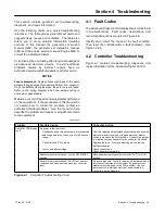
Figure 4-1 contains troubleshooting, diagnostic, and
repair information for the Advanced Digital Control.
Problem
Possible Cause
Corrective Action
Controller LED display
is off
No power to the controller:
Continuous power mode jumper is disconnected
and the generator set has not run for 48 hours or
longer.
Controller display will automatically activate when a remote
start command is received or the generator set master
switch is moved to the RUN position. Connect the jumper
to maintain continuous power to the controller, if desired.
Controller fuse (F3) is blown.
Replace the fuse. If the fuse blows again, contact the
distributor/dealer.
Low or no battery voltage.
Check connections.
Check generator set battery.
Generator set master switch is in the OFF/RESET
position.
Move generator set master switch to the AUTO or RUN
position.
Generator set master switch in AUTO but no start
command has been received since last controller
reset.
No action required. Controller display will activate when a
remote start command is received or the generator set
master switch is moved to the RUN position. Use the
remote switch to start generator set and activate the
controller display, if desired.
Figure 4-1
Controller Troubleshooting Chart
Содержание 4.5EFOD
Страница 1: ...Marine Generator Sets Models 6EOD 4 5EFOD 8 32EOZD 6 5 27EFOZD TP 6252 2 08c Operation ...
Страница 8: ...TP 6252 2 08 8 Safety Precautions and Instructions Notes ...
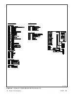
Страница 48: ...TP 6252 2 08 48 Section 5 Wiring Diagrams GM42202 E Figure 5 2 Wiring Diagram for Model 6EOD 4 5EFOD ...
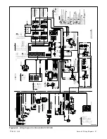
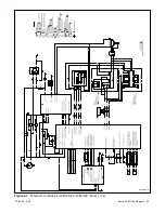
Страница 49: ...TP 6252 2 08 49 Section 5 Wiring Diagrams ADV7095A D Figure 5 3 Schematic for Model 6EOD 4 5EFOD Sheet 1 of 2 ...
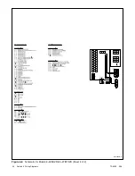
Страница 50: ...TP 6252 2 08 50 Section 5 Wiring Diagrams ADV7095B D Figure 5 4 Schematic for Model 6EOD 4 5EFOD Sheet 2 of 2 ...
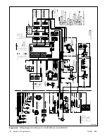
Страница 51: ...TP 6252 2 08 51 Section 5 Wiring Diagrams GM50490 B Figure 5 5 Wiring Diagram for Model 9EOZD 7EFOZD ...
Страница 58: ...TP 6252 2 08 58 ...
Страница 59: ...TP 6252 2 08 59 ...

