TP-6252 2/08
22 Section 2 Operation
2.7 Circuit Protection
If the generator set circuit breaker trips or the fuses blow
repeatedly, see Section 4, Troubleshooting, for possible
causes.
2.7.1 Line Circuit Breaker
A line circuit breaker interrupts the generator output in
the event of a fault in the wiring between the generator
and the load. The line circuit breaker location is shown
in Figure 1-1. If the circuit breaker trips, reduce the load
and switch the breaker back to the ON position.
2.7.2 Fuses
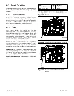
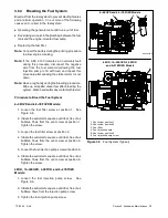
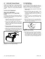
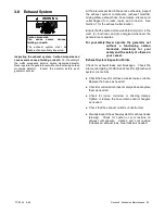
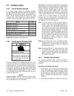
The engine harness (or junction box for the
6EOD/4.5EFOD and 9EOZD/7EFOZD models)
contains three 10-amp inline fuses. Always identify and
correct the cause of a blown fuse before restarting the
generator set. Refer to section 4, Troubleshooting, for
conditions that may indicate a blown fuse. Obtain
service from an authorized distributor/dealer.
Controller Fuse.
A replaceable 10-amp fuse protects
the controller circuitry. If the controller display is dark,
check the battery and battery connections and then
check the controller fuse. Replace the fuse if it is blown.
Relay Fuse.
A replaceable 10-amp fuse protects the
engine relays. If the generator set does not crank, check
the battery and battery connections and then check the
relay fuse. Replace the fuse if it is blown.
Auxiliary Winding Fuse.
A replaceable 10-amp fuse
protects the alternator.
Fuse
Label Location (*)
Auxiliary Winding
F1
Lead 55
Relay Interface Board
F2
Lead PF2
Controller
F3
Lead PF1
* See Figure 2-8 for the fuse location on 6EOD/4.5EFOD models or
See Figure 2-9 for the fuse location on 9EOZD/7EFOZD models.
Figure 2-7
Fuses
1
ADV7093A-A
1. Fuses
Figure 2-8
Fuse Location on 6EOD/4.5EFOD Model
1
ADV6967-A
1. Fuses
Figure 2-9
Fuse Location on 9EOZD/7EFOZD
Model
Содержание 4.5EFOD
Страница 1: ...Marine Generator Sets Models 6EOD 4 5EFOD 8 32EOZD 6 5 27EFOZD TP 6252 2 08c Operation ...
Страница 8: ...TP 6252 2 08 8 Safety Precautions and Instructions Notes ...
Страница 48: ...TP 6252 2 08 48 Section 5 Wiring Diagrams GM42202 E Figure 5 2 Wiring Diagram for Model 6EOD 4 5EFOD ...
Страница 49: ...TP 6252 2 08 49 Section 5 Wiring Diagrams ADV7095A D Figure 5 3 Schematic for Model 6EOD 4 5EFOD Sheet 1 of 2 ...
Страница 50: ...TP 6252 2 08 50 Section 5 Wiring Diagrams ADV7095B D Figure 5 4 Schematic for Model 6EOD 4 5EFOD Sheet 2 of 2 ...
Страница 51: ...TP 6252 2 08 51 Section 5 Wiring Diagrams GM50490 B Figure 5 5 Wiring Diagram for Model 9EOZD 7EFOZD ...
Страница 58: ...TP 6252 2 08 58 ...
Страница 59: ...TP 6252 2 08 59 ...


