

KGP-920
Chapter 8
Setup Procedure
93121662-00
8-1
Chapter 8 Setup Procedure
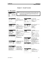
8.1 Menu options
1. Waypoints
Store, edit, copy and erase
waypoints (see pages 6-1 to
6-6)
2. Route
(See pages 6-13 to 6-17).
Store and erase a route.
Forward/backward navigation
Selection.
Automatic route switching.
Waypoint data switching.
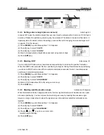
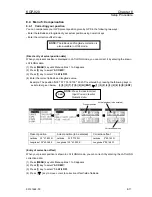
3. GPS
Display GPS satellite status.
Switch (2- and 3-dimensional)
positioning modes.
Select datum.
Set antenna height (above sea
level).
See DOP value to limit fix data
Set satellite elevation angle
limit.
Select RAIM function.
Select RAIM accuracy.
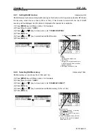
4. Differential GPS (DGPS)
Select DGPS style.
Select DGPS mode.
Set DGPS timeout
.
Select beacon station.
Set beacon frequency.
Select beacon bit rate.
Set DGPS input baud rate
.
m Monitor DGPS data.
Monitor beacon message.
NOTE
:
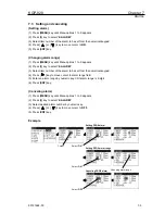
You can select an option from Menu in two ways: by direct numeric
key entry and by cursor shifting. This manual explains how to enter
numeric values for easy understanding, but you can also use the
cursor for option selection.
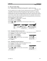
5. Compensation
Position correction (LAT/LONG,
LOPs)
Compass correction
Time difference
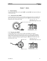
6. Alarm
(See pages 7-1 to 7-3)
Anchor watch alarm.
Proximity alarm.
XTE alarm.
CDI alarm.
Alarm message.
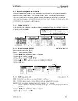
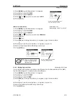
8. Initial value setup
Set average constants.
Select distance/speed units.
Select antenna height (above
sea level) units.
Select navigation mode.
Select position display mode
(LAT/ LONG, LOPs)
Select LAT/LONG display digits
Set chain.
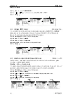
9. Interfacing
Select output format.
Edit the output format (IEC
61162-1).
Select ACK/ALR output
7. Calculation
Distance and bearing between
two
points
LAT/LONG into LOPs data
conversion
Calculation of estimated time
length
from the current position to the
destination, or required speed.
Содержание KGP-920
Страница 1: ......
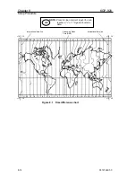
Страница 37: ...Chapter 5 KGP 920 Basic Operation 5 6 93121662 00 Page 4 Close up of PLOT screen...
Страница 128: ...KGP 920 Annex Annex Page No Local Geodetic Systems A 1 Decca zone A 3 93121662 00 Contents...
Страница 132: ......


