Vehicle Starting and Driving
S-22
3.
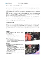
General state and tension of drive belts
Check the tension of engine belt, fan belt and compressor belt, if loose, tension it; if damaged, replace it.
Do not start up the engine without the drive belts. In the case of one of the belts breaking, immediately
stop the engine and have a new belt put in.
The checking, adjustment or substitution of the drive belts should be carried out with the engine shut
down.
Check cross plane of the belt for no cracks. Crackle in the transverse direction (along the belt width
direction) is acceptable while that in longitudinal direction and transverse crack cross is unacceptable.
Please replace the strap in case of abrasion or chip dropping off.
Too tight or too loose belt would make against proper operation of engine. Press belt to check tension.
Please refer to the manual book of engine assembly for detailed adjusting method and tension of belt.
The poli-V belts demand technical knowledge, therefore we recommend that this job, when necessary, be
carried out at a King-Long authorized Dealer or Workshop.
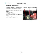
Ventilator drive belts
If it is necessary to replace the ventilator drive belts in emergency situations, adjust their tension in such a
way that upon pressing them with one’s thumb in the middle of the distance between the pulleys, a
defection of approximately 20mm is observed. Loosen fastening nut of intermediary pulley before turning
the adjusting bolt. After adjusting ventilator belt tension, tighten the fastening nut of intermediary pulley
firmly.
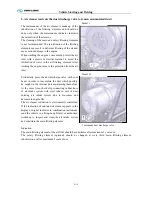
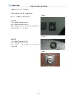
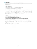
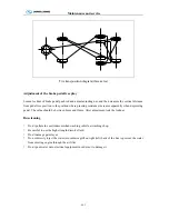
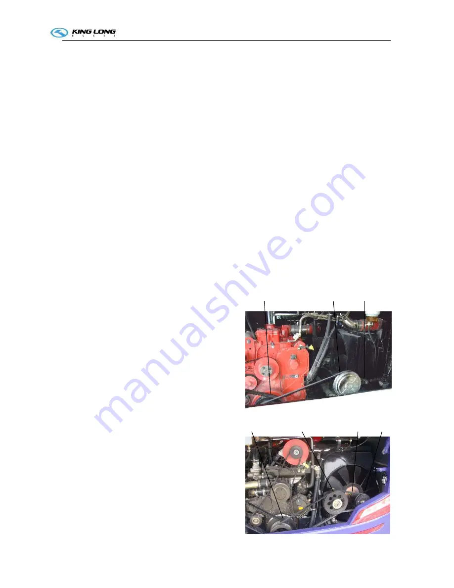
Model 1:
Adjusting method of the single belt driving fan belt is
shown in the figure
1. Check tension of belt
Apply force of 98N by the finger.
Strap sinkage between the crank pulley 1 and the fan
pulley 2 should be 25 ~ 31mm.
2. Adjust tension of cone belt
Adjust bolt 3 until the tension is proper.
The max offset angle of the fan pully shaft should not
exceed 5
°
, or else please replace it.
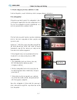
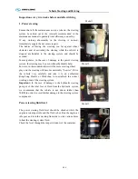
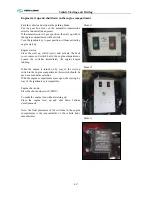
Model 2:
Adjusting method of the fan belt is shown in the figure
1. Check tension of belt
Apply force of 98N by the finger.
Strap sinkage between the crank pulley 4 and the counter
pulley 2 should be 25 ~ 31mm.
Strap sinkage between the counter pulley 2 and the fan
pulley 1 should be 7 ~ 8mm.
2. Adjust tension of cone belt
Adjust bolt 3 and counter pulley 2 up and down until the
tension is proper.
1
2
3
4
3
2
1
Содержание XMQ6127 series
Страница 18: ...Operation Instruction CI 1 Figure 17 Set MotPPR Figure 18 Clear Trip A Figure 19 Clear Trip B...
Страница 32: ...Operation Instruction P A 1 2 Control panel operation...
Страница 33: ...Operation Instruction P A 1...
Страница 34: ...Operation Instruction P A 1...
Страница 35: ...Operation Instruction P A 1...
Страница 36: ...Operation Instruction P A 1...
Страница 41: ...Operation Instruction 0 G 1 1 1 2 2 Pushbutton Settings...
Страница 42: ...Operation Instruction 0 G 1 1 2 Starting the Engine 1 3 Selecting the Gear...
Страница 43: ...Operation Instruction 0 G 1 1 4 Setting Off 1 5 Driving Ranges...
Страница 44: ...Operation Instruction 0 G 1 1 5 1 Downhill Travel 1 5 2 Downhill Travel 1 5 3 Kickdown...
Страница 46: ...Operation Instruction 0 G 1 1 6 Stopping Parking...
Страница 49: ...Operation Instruction 0 G 1 1 9 3 Actions to be Taken When the Relevant Permissible Oil Temperature is Exceeded...
Страница 50: ...Operation Instruction 0 G 1 1 10 Status Monitoring Warning Lamps 1 11 Transmission Response to a Malfunction...
Страница 51: ...Operation Instruction 0 G 1 1 11 1 Limp Home Mode 1 12 Auxiliary Control Unit...
Страница 52: ...Operation Instruction 0 G 1 1 12 1 Operating Instructions for the Auxiliary Control Unit...
Страница 53: ...Operation Instruction 0 AB 1 WABCO ABS BASIC INTRODUCTION...
Страница 54: ...Operation Instruction 0 AB 1...
Страница 55: ...Operation Instruction 0 AB 1...
Страница 56: ...Operation Instruction 0 AB 1...
Страница 57: ...Operation Instruction 0 AB 1...
Страница 58: ...Operation Instruction 0 EC 1 ECAS System Introduction 1 System introduction...
Страница 59: ...Operation Instruction 0 EC 1 3 System function...
Страница 60: ...Operation Instruction 0 EC 1...
Страница 77: ...Operation Instruction 0 E 1 CAN bus module...
Страница 158: ...Appendix A 4 Air braking schematic diagram...
Страница 159: ...A 5 Electric schematic diagram of the complete vehicle 1...
Страница 160: ...A 6 Electric schematic diagram of the complete vehicle 2...
Страница 161: ...A 7 Electric schematic diagram of the complete vehicle 3...
Страница 162: ...A 8 Electric schematic diagram of the complete vehicle 4...


