Operation Instruction
0-T-1
TOILET OPERATION
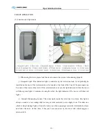
(1). Functions and Operations
①
.When using the toilet, please lock the door to ensure the system is functioning properly.
②
.Occupied Light: This indication light is controller by the toilet door lock. It can probably be
installed on the door of the toilet module, or be located at the front of the Coach. The passengers can
be aware of the status of the toilet. If the toilet module is vacant, the light indicator will not be on (or
will show green light.) if someone is using the toilet, the light indicator ill be on (or will show red
light.)
③
. Internal Illuminating System: The dome light inside the toilet has two status. One light is
always on and is a low wattage light so long as toilet module’s power supply is on. The other one,
which is a high wattage light, will only be turned on when a passenger enters the toilet module, closes
and locks the door. At that time, It has just been turned on by the door lock which triggers a
micro-switch.
Содержание XMQ6127 series
Страница 18: ...Operation Instruction CI 1 Figure 17 Set MotPPR Figure 18 Clear Trip A Figure 19 Clear Trip B...
Страница 32: ...Operation Instruction P A 1 2 Control panel operation...
Страница 33: ...Operation Instruction P A 1...
Страница 34: ...Operation Instruction P A 1...
Страница 35: ...Operation Instruction P A 1...
Страница 36: ...Operation Instruction P A 1...
Страница 41: ...Operation Instruction 0 G 1 1 1 2 2 Pushbutton Settings...
Страница 42: ...Operation Instruction 0 G 1 1 2 Starting the Engine 1 3 Selecting the Gear...
Страница 43: ...Operation Instruction 0 G 1 1 4 Setting Off 1 5 Driving Ranges...
Страница 44: ...Operation Instruction 0 G 1 1 5 1 Downhill Travel 1 5 2 Downhill Travel 1 5 3 Kickdown...
Страница 46: ...Operation Instruction 0 G 1 1 6 Stopping Parking...
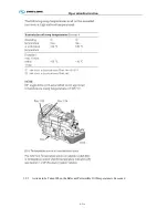
Страница 49: ...Operation Instruction 0 G 1 1 9 3 Actions to be Taken When the Relevant Permissible Oil Temperature is Exceeded...
Страница 50: ...Operation Instruction 0 G 1 1 10 Status Monitoring Warning Lamps 1 11 Transmission Response to a Malfunction...
Страница 51: ...Operation Instruction 0 G 1 1 11 1 Limp Home Mode 1 12 Auxiliary Control Unit...
Страница 52: ...Operation Instruction 0 G 1 1 12 1 Operating Instructions for the Auxiliary Control Unit...
Страница 53: ...Operation Instruction 0 AB 1 WABCO ABS BASIC INTRODUCTION...
Страница 54: ...Operation Instruction 0 AB 1...
Страница 55: ...Operation Instruction 0 AB 1...
Страница 56: ...Operation Instruction 0 AB 1...
Страница 57: ...Operation Instruction 0 AB 1...
Страница 58: ...Operation Instruction 0 EC 1 ECAS System Introduction 1 System introduction...
Страница 59: ...Operation Instruction 0 EC 1 3 System function...
Страница 60: ...Operation Instruction 0 EC 1...
Страница 77: ...Operation Instruction 0 E 1 CAN bus module...
Страница 158: ...Appendix A 4 Air braking schematic diagram...
Страница 159: ...A 5 Electric schematic diagram of the complete vehicle 1...
Страница 160: ...A 6 Electric schematic diagram of the complete vehicle 2...
Страница 161: ...A 7 Electric schematic diagram of the complete vehicle 3...
Страница 162: ...A 8 Electric schematic diagram of the complete vehicle 4...

