Maintenance and service
M-17
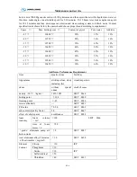
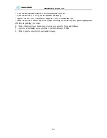
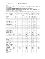
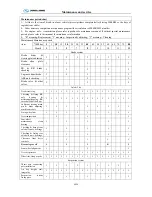
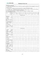
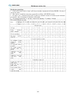
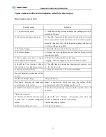
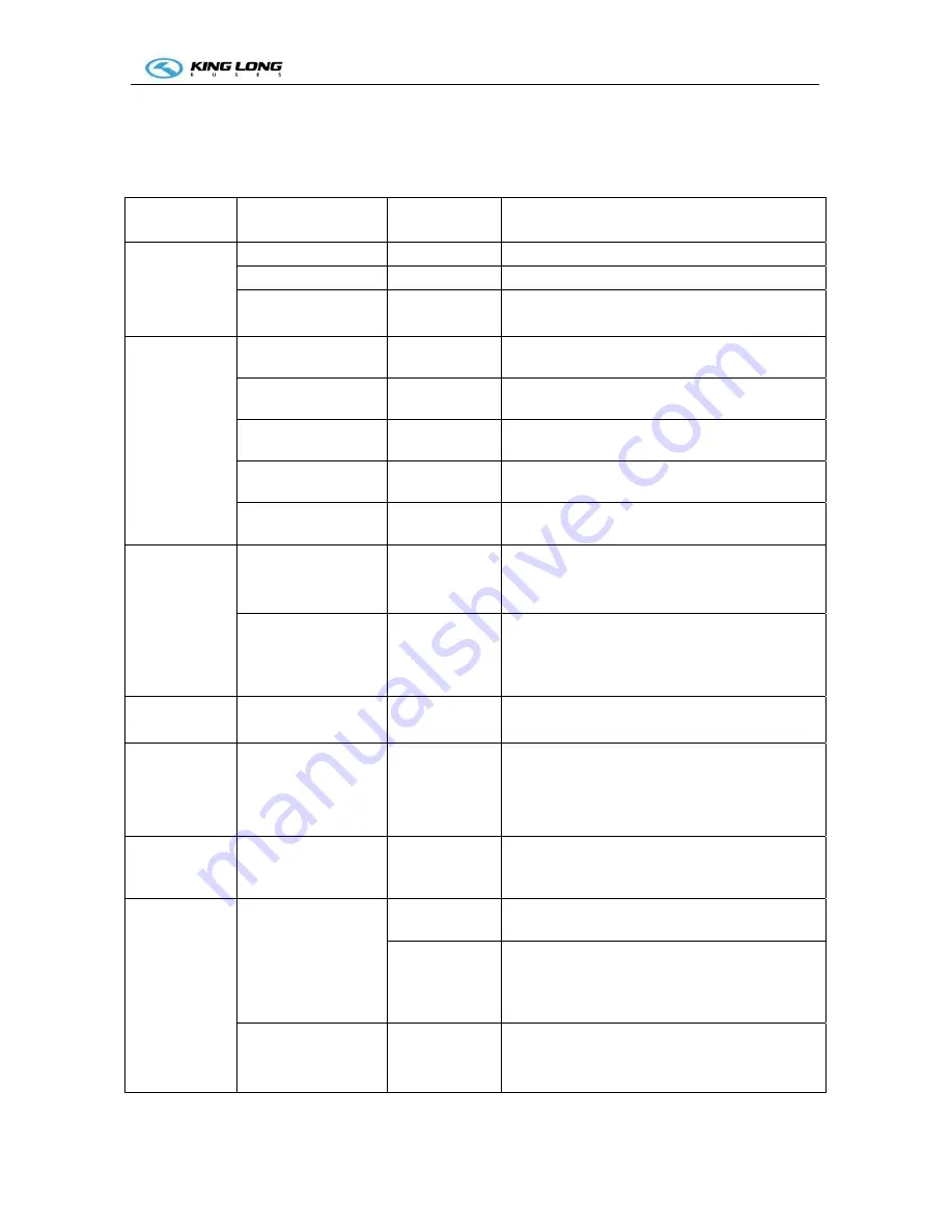
Maintenance operation and regulation every 20000km or 5 months depend on whichever occurs first.
Every 20000km include every 10000km maintenance operation
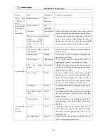
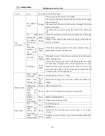
System Item
Operation
Technical
requirement
Engine
Fuel filter
Replace
Replace fuel filter element accordingly
Engine oil
Replace
Replace and fill oil level within required range
Coolant system –
anti-freezing
Check Check
the
density of anti-freezing
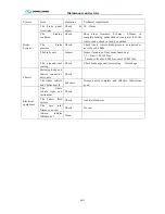
Propeller shaft
D
ust-proof cover
Check
Dust-proof cover without crack, damage, clip
reliable, bracket no loosening
Universal joint
condition
Check
Universal joint without loosening, no block
abnormal sound
Propeller shaft
bracket
Check
Propeller shaft bracket no loosening, screw torque
120
~
140Nm
Middle bearing
clearance
Check
Middle bearing clearance no more than 3mm
Lubricate
Lubricate
Lubricate each butter nozzle with 2# lithium
lubricant grease
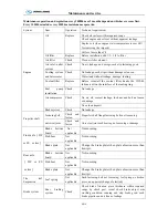
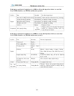
Steering system
GX85, GX 100, ZJ
100C
Change oil and
filter core of
oil tank
N32 which manufactured by Shanghai oi
refining factory or ATF or related products which
produced.
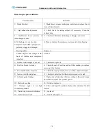
IPS40-SB8575D
series
Change oil and
filter core of
oil tank
Environment temperature >1
0℃,
adopt CD leve
15W/40 oil;
Environment temperature <1
0 ℃ ,
adopt No.8
hydraulic drive fluid
Front axle
Toe-in of front
wheel
Not applicable
Radial-ply tire: 0
~
+2mm
Rear axle
(
DF
& FS series
)
Final drive
Not applicable
From injection hole into final drive filling
Parathion-type 90 heavy-duty gear oil (GL-5)
to the face.
(
for first 1500km, than change for
every 24,000km
)
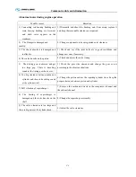
The leaf
suspension
Not
applicable
Not loosening, crack, fracture, misplacement,
screw U bolt, front 196
~
294Nm, rear 343
~
392Nm
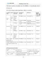
The air
suspension
The liner bushing of
the rod assembly
Change
The liner bushing is relative sliding with the bal
head
Change
The liner bushing is knocked to bend and the
tighten bolts of the adjustable rod are becoming
invalid which result to the threads of the ball head
and the steel pipe damaged.
The rubber ball joints
Change
The crack on the surface of the rubber is very
serious. The depth of the crack is up to 2mm and
the length of it is up to 8mm
Содержание XMQ6127 series
Страница 18: ...Operation Instruction CI 1 Figure 17 Set MotPPR Figure 18 Clear Trip A Figure 19 Clear Trip B...
Страница 32: ...Operation Instruction P A 1 2 Control panel operation...
Страница 33: ...Operation Instruction P A 1...
Страница 34: ...Operation Instruction P A 1...
Страница 35: ...Operation Instruction P A 1...
Страница 36: ...Operation Instruction P A 1...
Страница 41: ...Operation Instruction 0 G 1 1 1 2 2 Pushbutton Settings...
Страница 42: ...Operation Instruction 0 G 1 1 2 Starting the Engine 1 3 Selecting the Gear...
Страница 43: ...Operation Instruction 0 G 1 1 4 Setting Off 1 5 Driving Ranges...
Страница 44: ...Operation Instruction 0 G 1 1 5 1 Downhill Travel 1 5 2 Downhill Travel 1 5 3 Kickdown...
Страница 46: ...Operation Instruction 0 G 1 1 6 Stopping Parking...
Страница 49: ...Operation Instruction 0 G 1 1 9 3 Actions to be Taken When the Relevant Permissible Oil Temperature is Exceeded...
Страница 50: ...Operation Instruction 0 G 1 1 10 Status Monitoring Warning Lamps 1 11 Transmission Response to a Malfunction...
Страница 51: ...Operation Instruction 0 G 1 1 11 1 Limp Home Mode 1 12 Auxiliary Control Unit...
Страница 52: ...Operation Instruction 0 G 1 1 12 1 Operating Instructions for the Auxiliary Control Unit...
Страница 53: ...Operation Instruction 0 AB 1 WABCO ABS BASIC INTRODUCTION...
Страница 54: ...Operation Instruction 0 AB 1...
Страница 55: ...Operation Instruction 0 AB 1...
Страница 56: ...Operation Instruction 0 AB 1...
Страница 57: ...Operation Instruction 0 AB 1...
Страница 58: ...Operation Instruction 0 EC 1 ECAS System Introduction 1 System introduction...
Страница 59: ...Operation Instruction 0 EC 1 3 System function...
Страница 60: ...Operation Instruction 0 EC 1...
Страница 77: ...Operation Instruction 0 E 1 CAN bus module...
Страница 158: ...Appendix A 4 Air braking schematic diagram...
Страница 159: ...A 5 Electric schematic diagram of the complete vehicle 1...
Страница 160: ...A 6 Electric schematic diagram of the complete vehicle 2...
Страница 161: ...A 7 Electric schematic diagram of the complete vehicle 3...
Страница 162: ...A 8 Electric schematic diagram of the complete vehicle 4...

