Appendix
A-2
Tightening torque of main bolts and nuts
Position
Tightening torque
(
N·m
)
Front tyre nut
412
~
480
Rear tyre nut
294
~
421
Bolt, connecting lower knuckle and ball pin
245
~
304
Steering kingpin lockpin nut
60
~
70
Fixing nut, upper steering knuckle
274
~
343
Binding nut, tie rod
90
~
110
Locked bolt and nut between pitman arm and pitman arm shaft
407
~
434
Fixing nut, ball pin on both ends of drag rod
240
~
300
Steering gear fixing bolt
294
~
333
Steering gear lock nut
137
~
217
Upper fixing bolt and nut between steering bracket and frame
137
~
167
Lower fixing bolt and nut between steering bracket and frame
275
~
330
Final drive bevel gear flange nut
395
~
539
Fixing nut, Front brake backing plate
160
~
205
Fixing nut, Rear brake backing plate
196
~
245
Fixing bolt, between driven gear and differential
588
~
686
Differential housing nut
216
~
275
Fixing bolt, Front brake chamber bracket
59
~
79
Fixing bolt, Front brake chamber
40
~
59
Fixing bolt, Rear brake chamber
167
~
196
Fixing bolt, retarder housing
128
~
157
Fixing bolt, axle shaft
137
~
176
Drive gear bearing cap bolt
120
~
137
Rear axle oil level check plug
127
~
157
Lock bolt, front shoe axle
49
~
69
U bolt, front axle
196
~
294
U bolt, rear axle
343
~
392
Lower slotted nut, damper
134
~
167
Fixing nut, between damper and damper bracket
(
M20
)
88
~
118
Leaf spring pin locknut
54
~
69
Front engine mounting bracket bolt
90
~
110
Coupling bolt, between flywheel housing and frame bracket
80
~
100
Fixing bolt, between clutch and flywheel
90
~
100
Fixing bolt, between flywheel housing and clutch housing
60
~
75
Fixing bolt, between transmission and clutch housing
142
~
186
drive shaft coupling bolt
215
~
240
Fixing nut, transmission output shaft rear connecting panel
333
~
549
Содержание XMQ6127 series
Страница 18: ...Operation Instruction CI 1 Figure 17 Set MotPPR Figure 18 Clear Trip A Figure 19 Clear Trip B...
Страница 32: ...Operation Instruction P A 1 2 Control panel operation...
Страница 33: ...Operation Instruction P A 1...
Страница 34: ...Operation Instruction P A 1...
Страница 35: ...Operation Instruction P A 1...
Страница 36: ...Operation Instruction P A 1...
Страница 41: ...Operation Instruction 0 G 1 1 1 2 2 Pushbutton Settings...
Страница 42: ...Operation Instruction 0 G 1 1 2 Starting the Engine 1 3 Selecting the Gear...
Страница 43: ...Operation Instruction 0 G 1 1 4 Setting Off 1 5 Driving Ranges...
Страница 44: ...Operation Instruction 0 G 1 1 5 1 Downhill Travel 1 5 2 Downhill Travel 1 5 3 Kickdown...
Страница 46: ...Operation Instruction 0 G 1 1 6 Stopping Parking...
Страница 49: ...Operation Instruction 0 G 1 1 9 3 Actions to be Taken When the Relevant Permissible Oil Temperature is Exceeded...
Страница 50: ...Operation Instruction 0 G 1 1 10 Status Monitoring Warning Lamps 1 11 Transmission Response to a Malfunction...
Страница 51: ...Operation Instruction 0 G 1 1 11 1 Limp Home Mode 1 12 Auxiliary Control Unit...
Страница 52: ...Operation Instruction 0 G 1 1 12 1 Operating Instructions for the Auxiliary Control Unit...
Страница 53: ...Operation Instruction 0 AB 1 WABCO ABS BASIC INTRODUCTION...
Страница 54: ...Operation Instruction 0 AB 1...
Страница 55: ...Operation Instruction 0 AB 1...
Страница 56: ...Operation Instruction 0 AB 1...
Страница 57: ...Operation Instruction 0 AB 1...
Страница 58: ...Operation Instruction 0 EC 1 ECAS System Introduction 1 System introduction...
Страница 59: ...Operation Instruction 0 EC 1 3 System function...
Страница 60: ...Operation Instruction 0 EC 1...
Страница 77: ...Operation Instruction 0 E 1 CAN bus module...
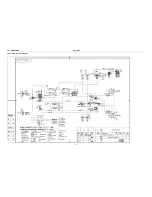
Страница 158: ...Appendix A 4 Air braking schematic diagram...
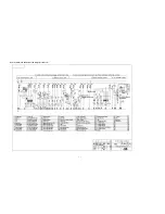
Страница 159: ...A 5 Electric schematic diagram of the complete vehicle 1...
Страница 160: ...A 6 Electric schematic diagram of the complete vehicle 2...
Страница 161: ...A 7 Electric schematic diagram of the complete vehicle 3...
Страница 162: ...A 8 Electric schematic diagram of the complete vehicle 4...

