Technical parameter and complete vehicle description
- 11 -
B. Hint:
a. The door remote control acts only when the parking brake is on the parking gear.
b. The door could only be opened when the external mechanical lock isn't locked up.
c. In order to avoid impact, make sure that the door is completed closed or opened, before you make the
next door switch operation.
Note: Deployment on the vehicle may be different with the above description because of different
deploying requirement of the clients.
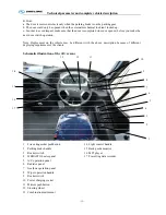
Schematic illustration of the driver zone
1
Fire extinguisher pushbutton
2
Parking brake handle
3
Rocker switch
4
WEBASTO heater panel
5
A/C operation panel
6
Radiator panel
7
Gearbox operation panel
8
Wiper operation handle
9
Rocker switch
10
Power charging socket
11
Mirrors pushbutton
12
Steering wheel
13
Combination instrument
14
Light control handle
15
Back guide monitor
16
MP3 player
17
Travelling data recorder
1
2
4
10
6
5
14
15
3
11
12
13
7
8
9
16
17
Содержание XMQ6127 series
Страница 18: ...Operation Instruction CI 1 Figure 17 Set MotPPR Figure 18 Clear Trip A Figure 19 Clear Trip B...
Страница 32: ...Operation Instruction P A 1 2 Control panel operation...
Страница 33: ...Operation Instruction P A 1...
Страница 34: ...Operation Instruction P A 1...
Страница 35: ...Operation Instruction P A 1...
Страница 36: ...Operation Instruction P A 1...
Страница 41: ...Operation Instruction 0 G 1 1 1 2 2 Pushbutton Settings...
Страница 42: ...Operation Instruction 0 G 1 1 2 Starting the Engine 1 3 Selecting the Gear...
Страница 43: ...Operation Instruction 0 G 1 1 4 Setting Off 1 5 Driving Ranges...
Страница 44: ...Operation Instruction 0 G 1 1 5 1 Downhill Travel 1 5 2 Downhill Travel 1 5 3 Kickdown...
Страница 46: ...Operation Instruction 0 G 1 1 6 Stopping Parking...
Страница 49: ...Operation Instruction 0 G 1 1 9 3 Actions to be Taken When the Relevant Permissible Oil Temperature is Exceeded...
Страница 50: ...Operation Instruction 0 G 1 1 10 Status Monitoring Warning Lamps 1 11 Transmission Response to a Malfunction...
Страница 51: ...Operation Instruction 0 G 1 1 11 1 Limp Home Mode 1 12 Auxiliary Control Unit...
Страница 52: ...Operation Instruction 0 G 1 1 12 1 Operating Instructions for the Auxiliary Control Unit...
Страница 53: ...Operation Instruction 0 AB 1 WABCO ABS BASIC INTRODUCTION...
Страница 54: ...Operation Instruction 0 AB 1...
Страница 55: ...Operation Instruction 0 AB 1...
Страница 56: ...Operation Instruction 0 AB 1...
Страница 57: ...Operation Instruction 0 AB 1...
Страница 58: ...Operation Instruction 0 EC 1 ECAS System Introduction 1 System introduction...
Страница 59: ...Operation Instruction 0 EC 1 3 System function...
Страница 60: ...Operation Instruction 0 EC 1...
Страница 77: ...Operation Instruction 0 E 1 CAN bus module...
Страница 158: ...Appendix A 4 Air braking schematic diagram...
Страница 159: ...A 5 Electric schematic diagram of the complete vehicle 1...
Страница 160: ...A 6 Electric schematic diagram of the complete vehicle 2...
Страница 161: ...A 7 Electric schematic diagram of the complete vehicle 3...
Страница 162: ...A 8 Electric schematic diagram of the complete vehicle 4...

