Vehicle Starting and Driving
S-14
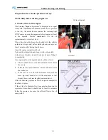
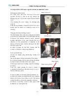
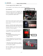
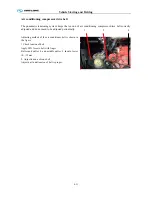
2. Air cleaner (activate the dust discharge valve to loosen accumulated dust)
The maintenance of the air cleaner is made up of the
substitution of the filtering elements and should be
done only when the maintenance indicator indicates
the saturation of the element.
The cleaning of the main and safety filtering elements
is not recommended. The re-utilization of the filtering
elements can result in deficient filtering of the air and
cause serious damage to the engine.
When washing the engine, conveniently protect the air
inlet with a plastic or similar material to avoid the
infiltration of water to the air filtering element. After
washing the engine, remove the protection from the air
inlet.
Periodically press the dust discharge valve with your
hand, in order to incomplete the dust which possibly
be caught in the internal part maintaining them clear.
At the same time, check clip connecting rubber hose
of air intake system with steel tube in case of dust
entering air intake system due to looseness and
decrease in engine life.
The air cleaner restriction is electronically controlled.
If the indication of saturated air cleaner appears in the
display of digital indicator in combination instrument,
send the vehicle to a King-Long Dealer or authorized
workshop to inspect and clean the air intake system
and substitute the main filtering element.
Indication
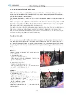
The main filtering element of the air filter should be substitutes after maximum 2 years use.
The safety filtering element (optional) should be changed at every third main filtering element
substitution, or after maximum 2 years of use.
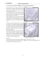
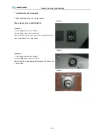
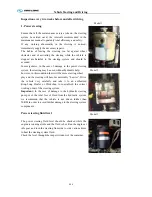
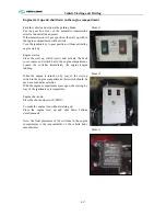
Model 1
Model II
1 automatic dust discharge valve
Содержание XMQ6127 series
Страница 18: ...Operation Instruction CI 1 Figure 17 Set MotPPR Figure 18 Clear Trip A Figure 19 Clear Trip B...
Страница 32: ...Operation Instruction P A 1 2 Control panel operation...
Страница 33: ...Operation Instruction P A 1...
Страница 34: ...Operation Instruction P A 1...
Страница 35: ...Operation Instruction P A 1...
Страница 36: ...Operation Instruction P A 1...
Страница 41: ...Operation Instruction 0 G 1 1 1 2 2 Pushbutton Settings...
Страница 42: ...Operation Instruction 0 G 1 1 2 Starting the Engine 1 3 Selecting the Gear...
Страница 43: ...Operation Instruction 0 G 1 1 4 Setting Off 1 5 Driving Ranges...
Страница 44: ...Operation Instruction 0 G 1 1 5 1 Downhill Travel 1 5 2 Downhill Travel 1 5 3 Kickdown...
Страница 46: ...Operation Instruction 0 G 1 1 6 Stopping Parking...
Страница 49: ...Operation Instruction 0 G 1 1 9 3 Actions to be Taken When the Relevant Permissible Oil Temperature is Exceeded...
Страница 50: ...Operation Instruction 0 G 1 1 10 Status Monitoring Warning Lamps 1 11 Transmission Response to a Malfunction...
Страница 51: ...Operation Instruction 0 G 1 1 11 1 Limp Home Mode 1 12 Auxiliary Control Unit...
Страница 52: ...Operation Instruction 0 G 1 1 12 1 Operating Instructions for the Auxiliary Control Unit...
Страница 53: ...Operation Instruction 0 AB 1 WABCO ABS BASIC INTRODUCTION...
Страница 54: ...Operation Instruction 0 AB 1...
Страница 55: ...Operation Instruction 0 AB 1...
Страница 56: ...Operation Instruction 0 AB 1...
Страница 57: ...Operation Instruction 0 AB 1...
Страница 58: ...Operation Instruction 0 EC 1 ECAS System Introduction 1 System introduction...
Страница 59: ...Operation Instruction 0 EC 1 3 System function...
Страница 60: ...Operation Instruction 0 EC 1...
Страница 77: ...Operation Instruction 0 E 1 CAN bus module...
Страница 158: ...Appendix A 4 Air braking schematic diagram...
Страница 159: ...A 5 Electric schematic diagram of the complete vehicle 1...
Страница 160: ...A 6 Electric schematic diagram of the complete vehicle 2...
Страница 161: ...A 7 Electric schematic diagram of the complete vehicle 3...
Страница 162: ...A 8 Electric schematic diagram of the complete vehicle 4...


