Operation Instruction
CI-1
Instruction of instrument
(VITI EDITION)
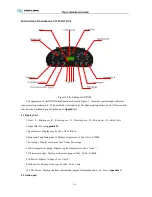
Figure-1 The Outline of ZB271M
The appearance of the ZB271M dashboard as shown in Figure-1 , it mainly contains eight indicator
type measuring instruments, 29 icons which were lighted by the light-emitting diodes, one LCD screen and
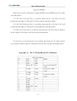
four buttons, dashboard pin definition go to
Appendix A
2.1 Display Part.
1.Gear P—Brake gear, R—Reverse gear
,
N—Neutral gear
,
D—Drive gear
,
S—Safety belt.
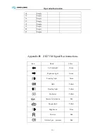
2.Signal Bar. Go to
Appendix B.
3.Speedometer .Display speed of bus. Units :Km/h.
4.BarometerI and Barometer II. Display air pressure of bus. Units: 0.1MPa .
5.Fuel gauge. Display amount of fuel. Units: Percentage.
6.Water temperature gauge .Display engine temperature of bus. Units:
℃
.
7.Oil pressure gauge. Display oil pressure gauge of bus. Units : 0.1MPa.
8.Voltmeter .Display Voltage of car. Unit: V.
9.Tachometer .Display rotate speed of bus. Units: r/min.
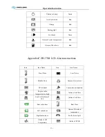
10.LCD Screen. Display interface information, engine information and so on. Go to
Appendix C
.
2.2 Button part
Содержание XMQ6127 series
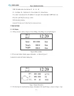
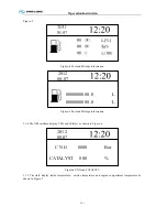
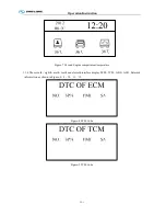
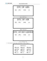
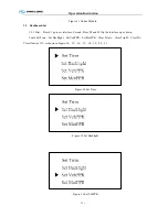
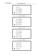
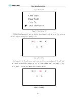
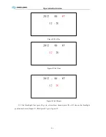
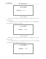
Страница 18: ...Operation Instruction CI 1 Figure 17 Set MotPPR Figure 18 Clear Trip A Figure 19 Clear Trip B...
Страница 32: ...Operation Instruction P A 1 2 Control panel operation...
Страница 33: ...Operation Instruction P A 1...
Страница 34: ...Operation Instruction P A 1...
Страница 35: ...Operation Instruction P A 1...
Страница 36: ...Operation Instruction P A 1...
Страница 41: ...Operation Instruction 0 G 1 1 1 2 2 Pushbutton Settings...
Страница 42: ...Operation Instruction 0 G 1 1 2 Starting the Engine 1 3 Selecting the Gear...
Страница 43: ...Operation Instruction 0 G 1 1 4 Setting Off 1 5 Driving Ranges...
Страница 44: ...Operation Instruction 0 G 1 1 5 1 Downhill Travel 1 5 2 Downhill Travel 1 5 3 Kickdown...
Страница 46: ...Operation Instruction 0 G 1 1 6 Stopping Parking...
Страница 49: ...Operation Instruction 0 G 1 1 9 3 Actions to be Taken When the Relevant Permissible Oil Temperature is Exceeded...
Страница 50: ...Operation Instruction 0 G 1 1 10 Status Monitoring Warning Lamps 1 11 Transmission Response to a Malfunction...
Страница 51: ...Operation Instruction 0 G 1 1 11 1 Limp Home Mode 1 12 Auxiliary Control Unit...
Страница 52: ...Operation Instruction 0 G 1 1 12 1 Operating Instructions for the Auxiliary Control Unit...
Страница 53: ...Operation Instruction 0 AB 1 WABCO ABS BASIC INTRODUCTION...
Страница 54: ...Operation Instruction 0 AB 1...
Страница 55: ...Operation Instruction 0 AB 1...
Страница 56: ...Operation Instruction 0 AB 1...
Страница 57: ...Operation Instruction 0 AB 1...
Страница 58: ...Operation Instruction 0 EC 1 ECAS System Introduction 1 System introduction...
Страница 59: ...Operation Instruction 0 EC 1 3 System function...
Страница 60: ...Operation Instruction 0 EC 1...
Страница 77: ...Operation Instruction 0 E 1 CAN bus module...
Страница 158: ...Appendix A 4 Air braking schematic diagram...
Страница 159: ...A 5 Electric schematic diagram of the complete vehicle 1...
Страница 160: ...A 6 Electric schematic diagram of the complete vehicle 2...
Страница 161: ...A 7 Electric schematic diagram of the complete vehicle 3...
Страница 162: ...A 8 Electric schematic diagram of the complete vehicle 4...

