Assembly Instructions
Perks
Proper product installation, in accordance with these instructions, is the responsibility of the installing agent.
If you have any questions concerning these instructions, please call Kimball Office Customer Service.
Part No. 2066774
Revision A-08
Page 1 of 1
Field Installed Grommet
Tools Required
■
Tape Measure
■
Rubber Mallet
■
Hole Saw
■
Power Drill
■
Drill Bit - As Required
Package Contents
■
Grommet (qty. per order)
General Information
■
Grommets can be located in any worksurface.
■
Check for clearance under worksurface
BEFORE
boring to
avoid brackets, panels or similar interferences.
Installation
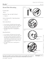
1. Verify the model number for the grommet being installed
and note appropriate drill bit to be used. (Figure A).
2. Prepare face side of surface (drilling side) by placing
masking tape or similar material over area to be drilled to
prevent tear out. Measure and mark grommet location not-
ing minimum distances recommended from the edge of the
core material or adjacent worksurface. Using specified drill
bit, bore hole through worksurface as shown. (Figure B).
3. Place grommet in hole. As required, use rubber mallet to
secure grommet into place by tapping grommet along its
outer edges, not in the center. Install grommet cap.
Figure A
P
ri
n
te
d
in
U
.S
.A
.
©
2
0
0
8
K
im
b
a
ll
In
te
rn
a
ti
o
n
a
l,
In
c
.
T
8
0
0
.4
8
2
.1
8
1
8
F
8
1
2
.4
8
2
.8
3
0
0
TM
99KG50
2 " Drill Bit
99KG60
2
5
⁄
16
" Drill Bit
99KG80
3
1
⁄
8
" Drill Bit
99KG7
2
5
⁄
16
" Drill Bit
Figure B
User Side
7
1
⁄
4
"
36"
7
1
⁄
4
"
30 "
24"
User Side
User Side
Series
A
B
C
D
E
F
Dimensions
Definition
Evoke
Prevail
Priority
Footprint
5"
5"
5"
5"
5"
5"
A
B
F
C
E
D
Transcend
7
1
⁄
2
"
3
3
⁄
8
"
3
3
⁄
8
"
7
1
⁄
2
"
3
3
⁄
8
"
3
3
⁄
8
"
7
23
⁄
32
"
3
5
⁄
16
"
3
5
⁄
16
"
9
1
⁄
16
"
3
5
⁄
16
"
3
5
⁄
16
"
5
3
⁄
8
"
14
1
⁄
8
"
5
3
⁄
8
"
5
3
⁄
8
"
14
1
⁄
8
"
14
1
⁄
8
"
9
3
⁄
8
"
3
3
⁄
8
"
3
3
⁄
8
"
9
3
⁄
8
"
3
3
⁄
8
"
3
3
⁄
8
"
5"
5"
5"
5"


