Assembly Instructions
Perks
™
Proper product installation, in accordance with these instructions, is the responsibility of the installing agent.
If you have any questions concerning these instructions, please call Kimball Office Customer Service.
Part No. 2040774 Revision A-07
Page 1 of 1
Carousel Tray
Tools Required
I
Drill
I
Phillips Head Screwdriver
I
1
⁄
8
" Bit and
1
⁄
2
" Socket
Package Contents
I
Carousel Tray
I
1 Standard Washer
I
Mounting Plate
I
1 Lock Nut
I
4 #8 x
3
⁄
4
" Flathead Screws
I
Roller Catch Assembly
I
2 #8 x 1
1
⁄
2
" Panhead Screws
General Information
I
These instructions provide the basic information to install
a Carousel Tray onto any worksurface.
Installation
Carousel Tray:
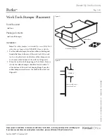
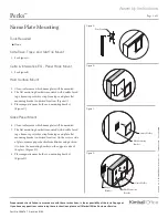
1. Position mounting plate 1" from front edge of worksurface
in desired location. (Figure A).
2. Secure bracket with four flathead screws provided.
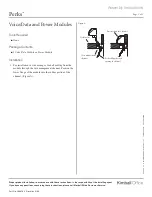
3. Align hole in tray over threaded stem on mounting plate.
4. Assemble washer then lock nut and tighten with
1
⁄
2
" socket.
Roller Catch:
Note:
Roller catch stabilizes carousel tray at rear, preventing it
from unintentional free-rotation, e.g. if accidentally bumped.
1. Align Carousel Tray with front edge of worksurface.
Position roller catch inside depression at center back of tray.
(Figure B).
2. Mark worksurface through holes in bracket. Drill two
pilot holes and mount bracket to worksurface with two
1
1
⁄
2
" panhead screws provided.
Figure A
Figure B
Lock Nut
Mounting
Plate
Carousel
Tray
Printed in U.S.A.
© 2007 Kimball Inter
national, Inc.
T 800.482.1818
F 812.482.8300
Washer
Roller Catch
1
1
⁄
2
" Panhead Screws
Position front edge of
tray parallel with front
edge of worksurface
Position Roller Catch
in depression in back
of tray


