background image

4

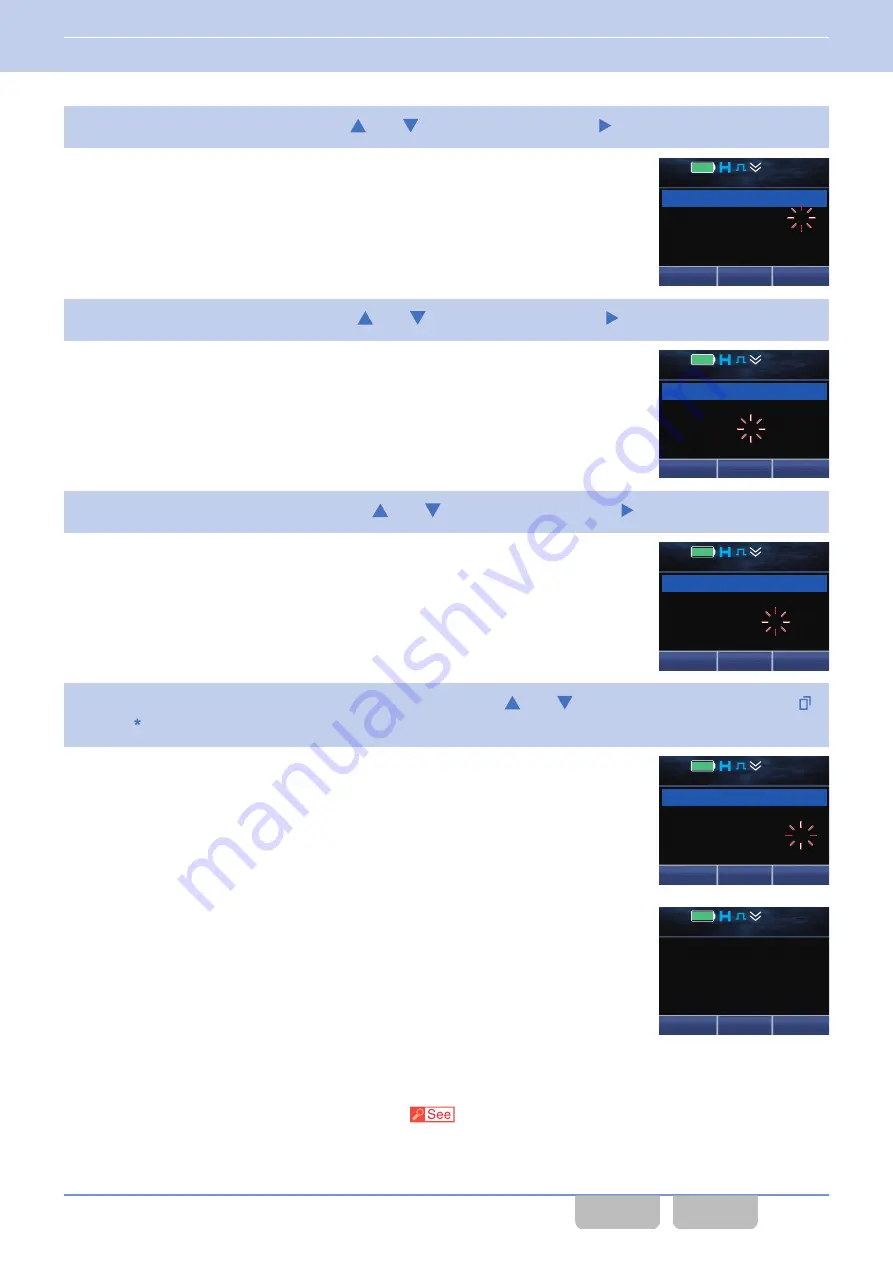
Configure the day by pressing the 

[

]

 or 

[

]

 key, and then press the 

[

]

 key.

5

Configure the hour by pressing the 

[

]

 or 

[

]

 key, and then press the 

[

]

 key.

6

Configure the minute by pressing the 

[

]

 or 

[

]

 key, and then press the 

[

]

 key.

7

Configure the display format for the time by pressing the 

[

]

 or 

[

]

 key, and then press the 

Menu

 (

[

]

)

or 

[ ]

 key.

A Key Beep C (3 beeps) sounds from the transceiver, and then the date
and time is determined.

12 : 34

A

M

Date       14/05/20

Time       12:34 PM

Back

OK

Clock Adjust

12 : 34

A

M

Date       14/05/20

Time        1:34 PM

Back

OK

Clock Adjust

12 : 34

A

M

Date       14/05/20

Time        1:35 PM

Back

OK

Clock Adjust

12 : 34

A

M

Date       14/05/20

Time        1:35 AM

Back

OK

Clock Adjust

Menu

Zone+

Zone 1

Channel 1

  1 : 35

P

M

Configuration using KPG-D1/ D1N

Assigning functions to the 

PF

 keys on the transceiver (

 Transceiver Settings > Key Assignment)

14 ADJUSTING THE TIME ON THE TRANSCEIVER

14.2 Adjusting the Time

Common FUNC (K, F)/Ver 2.20

239

CONTENTS

INDEX

Содержание NX-5800

Страница 1: ... NX 5000 series Common Function Reference Common FUNC Version 2 20 Last Updated June 30 2017 Language English Type K F 2017 ...

Страница 2: ...sceiver to a PC 21 2 2 Connecting the Transceiver to a PC by Bluetooth 22 2 3 Writing the Configuration Data to the Transceiver 22 Writing configuration data to multiple transceivers using Bluetooth communication 23 About the writing of configuration data in a Multi RF Deck Multi Control Head structure 23 2 4 Reading the Configuration Data from the Transceiver 23 2 5 Embedding a Message in the Tra...

Страница 3: ...CEPTION 77 4 1 Transmit Receive Frequencies 77 4 2 Transmit Power 77 4 3 Channel Spacing 80 4 4 Beat Shift 82 4 5 Displaying the Signal Strength Level RSSI Level BER Maintenance Display 83 5 INDICATION AND DISPLAY 88 5 1 Busy LED 88 5 2 Transmit LED 88 5 3 Selective Call Alert LED 89 5 4 Optional Signaling LED 90 5 5 Lighting the Backlight Backlight 91 5 6 Changing the Brightness of the Backlight ...

Страница 4: ... 142 7 BATTERY 144 7 1 Displaying the Remaining Battery Power Level Battery Indicator 144 7 2 Warning that the Battery Voltage Is Low Battery Warning 145 7 3 Warning the Battery Power of the Vehicle Battery Is Low Battery Warning 146 7 4 Displaying the Remaining Battery Power by Operating the Transceiver Battery Status 146 7 5 Reducing Battery Consumption Battery Saver 147 7 6 Displaying the Remai...

Страница 5: ...n Connecting to a Bluetooth compatible Device Fails Headset Profile 201 10 6 About Serial Port Profile SPP Connection SPP Disconnection 202 Connecting by Serial Port Profile 202 Resetting the Connection by Serial Port Profile 203 Behavior of the Transceiver When Connecting to a Bluetooth compatible Device Fails Serial Port Profile 203 10 7 Switching the Speaker to Emit Audio Bluetooth Speaker 204 ...

Страница 6: ...rd When Reading Configuration Data in a PC Read Authorization Password 235 13 3 Password for Writing Configuration Data Overwrite Password 236 14 ADJUSTING THE TIME ON THE TRANSCEIVER 237 14 1 Displaying the Current Time 237 14 2 Adjusting the Time 238 15 MODE 240 15 1 Testing the Transmit and Receive Capabilities of the Transceiver Panel Test Mode 240 15 2 Adjusting the Transmit and Receive Capab...

Страница 7: ... 16 9 Communication Ports 296 PC Interface Protocol 297 16 10 External Ports AUX Input Output 297 Restrictions When Configuring AUX Input Output 298 16 11 Ignition Sense 299 Behaviors of Each Ignition Terminal 299 16 12 Microphone hook 300 16 13 GPS 300 16 14 Scan 301 16 15 Communications in an Emergency Emergency 302 16 16 Bluetooth Communication 303 Bluetooth On Off 305 Finding a Bluetooth compa...

Страница 8: ... a Multi RF Deck System 378 Configuration in KPG D1 D1N if RF Decks Are Switched 381 Configuration in KPG D1 D1N If Control Heads Are Switched 384 Configuration in KPG D1 D1N If Changed from a Multi RF Deck System to a Single RF Deck Structure 385 17 12 About the Message Display 386 17 13 About the Pin Arrangement for KCT 72 and the Connection of External Devices 387 Connecting the External Speake...

Страница 9: ... the transceiver ON while pressing and holding the Menu Q key causes the transceiver to display Radio Mode Selection Then if Transceiver Info is selected and the Menu Q key is pressed the transceiver enters Transceiver Information Mode and then the firmware version can be viewed Version of KPG D1 KPG D1N V 2 20 Can be viewed in the About KPG D1 dialog box or About KPG D1N dialog box of KPG D1 KPG ...

Страница 10: ...LS OR RESTRICTIONS MUST FULLY COMPLY WITH ANY EXPORT AND IMPORT LAWS AND REGULATIONS OF THE COUNTRY OR REGION AND OBTAIN ALL REQUIRED AUTHORIZATIONS OR LICENSES IN ADVANCE How to Read the In depth Manual The In depth Manual has the following sections Common Function Reference Common FUNC Describes the functions common to the transceivers Analog Function Reference Analog FUNC Describes the analog f...

Страница 11: ...r describing the key that is assigned with any function When the Reset function is assigned to the A key the A key is described as the Reset key Notations for FPU names KPG D1 and KPG D1N are referred to collectively as KPG D1 D1N in this document About the Notation of the Supported Models This manual describes the supported models according to the following rules Model Name Notation NX 5200 Porta...

Страница 12: ...rol DTMF Dual Tone Multi Frequency ESN Electronic Serial Number ETX The end of Text FCC Federal Communications Commission FPU Field Programming Unit GPS Global Positioning System HSP Headset Profile ID Identification LOK Link OK connected to the repeater MI2 Microphone Input II Mic Microphone NAC Network Access Code OST Operator Selectable Tone P25 APCO Project 25 PA Public Address PF Programmable...

Страница 13: ...he firmware is strictly prohibited without prior written consent of JVC KENWOOD Corporation Furthermore any reselling assigning or transferring of the firmware is also strictly prohibited without embedding the firmware in KENWOOD product memories Firmware is equipped with the AMBE 2 voice encoding technology under license from Digital Voice Systems About Trademarks and Patent Rights Adobe and Adob...

Страница 14: ...eference in the help texts of KPG D1 D1N is described Therefore you can configure the function by referring to the function also appearing in the help texts of KPG D1 D1N About the Zone channel Format Using KPG D1 D1N the zone information of the transceiver can be configured by selecting whether to configure for each zone the channels in the same communication system Analog Conventional P25 Conven...

Страница 15: ...g Unit ID Own Transceiver Settings Personal System Information NXDN Conventional Unit ID Own In this case if NXDN Conventional is selected in System Type of System Information Unit ID Own can be configured in an NXDN Conventional system Refer to the help texts of KPG D1 D1N for the method of System Type configuration using KPG D1 D1N About Multi RF Deck Multi Control Head For Mobile by connecting ...

Страница 16: ...e 0 KMC 27A Microphone 0 KMC 27B Microphone 0 KMC 28A Microphone with 12 Keypad 0 KMC 35 Microphone 0 KMC 36 Microphone with 12 Keypad 0 KCT 73MIC External Microphone 0 KMC 9C Desktop Microphone 0 KMC 53 Desktop Microphone 0 KES 3 External Speaker 0 KES 5 External Speaker 0 KAP 2 PA HA Unit 0 KCT 18 Ignition Sense Cable 0 KCT 46 Ignition Sense Cable 0 KRA 40 GPS Antenna 0 KWD AE30 Secure Cryptogra...

Страница 17: ...cies such as if other transceivers transmit 0 If even transmit and receive frequencies other than the above the GPS receiver may be unable to position if frequencies emitted from other transceivers and electronic equipment interfere within the GPS receive frequency range 0 As the built in GPS receiver unit consumes more power when powered on compared to when powered off the battery life of the tra...

Страница 18: ...vious Page To return to the previous page click the Previous Page button on your Adobe Acrobat or Adobe Reader or press the M key while pressing and holding the Alt key on the keyboard Search the Text The text in this document can be searched using the search function of your Adobe Acrobat or Acrobat Reader Open the Reference in Another FUNC In this manual a reference to other FUNC is written as N...

Страница 19: ...Built in Bluetooth 0 microSD card slot 0 Motion Sensor Others 0 Date 12 24 Hour Time Clock 0 Flash Firmware Upgrading Mobile 0 128 Zones 512 Channels per zone 1 Models 0 VHF Models Low 5 W High 50 W 0 UHF Models Low 5 W High 45 W 0 700 MHz 800 MHz Model Low 2 W High 30 W 35 W Display Functions 0 Color LCD 0 7 Color LED 0 Function Status LCD Icons 0 Transmit Busy Call Alert Warn LED Specifications ...

Страница 20: ...Trunking P25 Phase 2 Trunking 0 Paging Call 0 Telephone Call 0 Priority Monitor Scan 0 Limited Talkgroup Scan NXDN DIGITAL MODES GENERAL 0 NXDN Digital Air Interface 0 AMBE 2 VOCODER 0 6 25 kHz Very Narrow 12 5 kHz Narrow Channel Spacing 0 Over the Air Alias 0 Paging Call 0 Emergency Call 0 All Group Call 0 Status Message 3 0 Remote Stun Kill 2 0 Remote Monitor 2 0 Short Long Messages 3 0 AUX Inpu...

Страница 21: ...E 2 VOCODER 0 12 5 kHz Channel Spacing 0 Color Code 0 Individual Call 0 Paging Call 0 Group Call Broadcast Call 0 Unaddressed Call 0 Emergency Call 0 All Group Call 0 Status Message 3 0 Short Messages 3 0 AUX Input Status Message Mobile Only 4 0 AUX Output Status Message Mobile Only 5 0 Open Voice Channel Mode OVCM 0 Call Interruption 0 Remote Control 0 Ignition On Off GPS Reporting Mobile only 0 ...

Страница 22: ...2 The supported PC software and external devices need to be separately prepared for the transmitting transceiver 3 To send messages or data with serial communications the supported PC software and external devices need to be separately prepared for the transmitting transceiver In addition to send the received messages or data to external devices the supported PC software and external devices need ...

Страница 23: ...e Function Modes for using Mode Reset Timer to Table 3 3 17 Added Direct Channel OST to Table 3 4 18 Added the description of the analog system in Manual Dialing 19 Added the description of the analog system and Table 3 6 in 3 7 Viewing the Receive History Stack 20 Added Scroll Display in 3 8 Operating the Transceiver in Each Mode Common Operation 21 Added the following items to Table 3 8 0 Volume...

Страница 24: ...tooth Discoverable 46 Added the descriptions of Headset Profile and Serial Port Profile in Receiving a Pairing Request from a Bluetooth compatible Device 47 Corrected the descriptions on the available operations in 10 4 Displaying a Bluetooth compatible Device Bluetooth My Devices 48 Added the description on the volume level of the received audio of a Bluetooth compatible device in Connecting by H...

Страница 25: ...tion Confirmed Tone Record Stopped Tone 18 Added the description of the following tones to Table 6 4 Advanced GPS Report Error Tone Low SD Memory Tone 19 Added the description of various Alert Tones in a DMR Conventional system to Table 6 10 20 Added 6 8 Using Voice Guidance Voice Announcement 21 Added the description of the specifications in a DMR Conventional system in 7 5 Reducing Battery Consu...

Страница 26: ...e 3 11 9 Added the description of KCH 21R Handheld Control Head to 5 5 Changing the Brightness of the Backlight LCD Brightness 10 Added the note in 5 7 Automatically Adjusting the Brightness Level of the LCD Auto Dimmer 11 Added the size of the bitmap image that can be used for KCH 21R Handheld Control Head to 5 12 Displaying a Bitmap Image When the Transceiver is Turned ON Custom Start up Screen ...

Страница 27: ...o the configuration items in Table 3 18 11 Added the description of a DMR Conventional system in 4 4 Beat Shift 12 Changed 4 5 Displaying the Signal Strength Level RSSI Level Maintenance Display to 4 5 Displaying the Signal Strength Level RSSI Level BER Maintenance Display Added the description related to the BER display 13 Added 5 4 Optional Signaling LED 14 Added the Encryption ARC4 icon to Tabl...

Страница 28: ...ording Received Audio Automatically Auto Recording 31 Added the description of DMR Conventional in the following items of Table 19 1 Added Manual Site Hunt Group Group Short Message Group Status Individual Individual Short Message Individual Status Short Message Status 32 Added Manual Site Hunt to Table 19 1 33 Corrected the description of Speaker Attenuation in Table 19 1 This function can be ass...

Страница 29: ...G D1 D1N the configuration data can be changed or written to another transceiver Reading the Configuration Data from the Transceiver Page 23 Transmission Reception Changing Transmit Power The transmission power of the transceiver can be changed to high power medium power or low power Transmit Power Page 77 Changing the Input Sensitivity of the Microphone The input sensitivity of the microphone can...

Страница 30: ...ones sound from the transceiver according to the operation of the transceiver Tones that Sound When a User Operates the Transceiver or When the Transceiver Status Is Changed Page 105 Changing the Calling Alert Tone Tones that sound from the transceiver when the transceiver receives a call using optional signaling or a status message can be changed to the desired tone Tones that Sound When the Tran...

Страница 31: ...Deck system can be structured MULTI RF DECK MULTI CONTROL HEAD Page 247 Other Convenient Functions Locking the Transceiver Keys By locking the transceiver keys a user can avoid erroneous operation of the transceiver caused by physically contacting the transceiver while carrying it around the waist etc Locking the Transceiver Keys Key Lock Page 70 Reducing Battery Consumption Portable Only The powe...

Страница 32: ...ll be changed to the active state F Side 1 Key The preassigned function will be activated or will be changed to the active state G Speaker The received audio and the Alert Tone sound from the speaker H PTT Switch Pressing the PTT switch allows transmitting I Built in Microphone J LCD The channel number and the transceiver s status appear on this display K Side 2 Key The preassigned function will b...

Страница 33: ...ion will be activated or will be changed to the active state In this manual the W Function key is described as the Function W key R T Home Key The preassigned function will be activated or will be changed to the active state In this manual the T Home key is described as the Home T key S Keypad The transceiver can be operated by pressing a key T A B C Key The preassigned function will be activated ...

Страница 34: ...e Key The preassigned function will be activated or will be changed to the active state In this manual the T Home key is described as the Home T key I Q Menu Key The preassigned function will be activated or will be changed to the active state In this manual the Q Menu key is described as the Menu Q key The default of the Q Menu key is the Menu function If the configuration is changed using KPG D1...

Страница 35: ...the luminance of the LCD depending on the brightness of the environment I Transmit LED This LED lights when the transceiver transmits a signal J Busy Status LED This LED lights or flashes according to the status such as while the transceiver is receiving a signal and when the transceiver receives a call K T Home Key The preassigned function will be activated or will be changed to the active state ...

Страница 36: ...eassigned function will be activated or will be changed to the active state Q Volume Control The volume level of the speaker sound can be adjusted R Selector The preassigned function will be activated or will be changed to the active state It is normally used to change the zone or channel 1 FUNCTIONS AND PANEL LAYOUT 1 2 NX 5700 NX 5800 NX 5900 Common FUNC K F Ver 2 20 5 CONTENTS INDEX ...

Страница 37: ...l be activated or will be changed to the active state F Built in Microphone G Speaker The received audio and the Alert Tone sound from the speaker H LCD The channel number and the transceiver s status appear on this display I G H Key The preassigned function will be activated or will be changed to the active state It is normally used to change the zone or channel J Q Menu Key The preassigned funct...

Страница 38: ...andheld Control Head Side View P Side 1 Key The preassigned function will be activated or will be changed to the active state Q PTT Switch Pressing the PTT switch allows transmitting R Side 2 Key The preassigned function will be activated or will be changed to the active state S Side 3 Key The preassigned function will be activated or will be changed to the active state T Key The preassigned funct...

Страница 39: ...transmitting B PF 1 Key The preassigned function will be activated or will be changed to the active state C PF 2 Key The preassigned function will be activated or will be changed to the active state 1 FUNCTIONS AND PANEL LAYOUT 1 2 NX 5700 NX 5800 NX 5900 Common FUNC K F Ver 2 20 8 CONTENTS INDEX ...

Страница 40: ... Individual Call Mode and Status Mode The number such as the list number or channel number appears at the right end of the title line XXXXX XXXXX XXXXX XXXXX XXX XXX XXX 12 34 A M Icon Title 18 characters Line 2 18 characters Key Guide 6 characters Clock Line 1 18 characters Line 3 18 characters 0 Function Mode Frame 2 This frame is used to display the Function Mode such as Status Mode The number ...

Страница 41: ...occurs Menu XXXXX XXXXX XXXXX XXXXX 12 34 A M Zone Mobile KCH 19 Basic Panel 0 Basic Frame This frame is used to display the name such as the channel name Various icons indicating the transceiver s status appear in the icon display area 12 34A M XXX XXX XXX XXX XXXXXX XXXXX XXXXX 12 34A M XXX XXX XXX XXX XXXXXX XXXXX XXXXXXXXXXXXXX XXXXXXXXXXXXXXXXXX Icon Sub Display 6 characters Main LCD 14 chara...

Страница 42: ...XX XXXXXXXXXXXXXX XXXXXXXXXXXXXX Icon Title 32 characters Line 1 22 characters Key Guide 6 characters Clock Line 2 22 characters 0 Category Icon Frame This frame is used to display the Menu Category in Icon Mode 12 34A M XXX XXX XXX XXX XXXXXXXXXXXXXX XX Icon Category Icon Category Name 18 characters List Number Key Guide 6 characters Clock 0 Message Frame This frame is used to display the message...

Страница 43: ...XXXXXXXXXXXXXX Icon Clock Title 32 characters Line 1 22 characters Key Guide 6 characters Line 2 22 characters Line 3 22 characters Line 4 22 characters 0 Function Mode Frame 2 This frame is used to display the Function Mode such as Status Mode The number such as the list number or channel number appears at the right end of the title line The icon can be displayed at the right side of each line 12...

Страница 44: ...XXXXXXXXXXXXX XXXXXX XXXXXXXXXXXXXX XXXXXX XXXXXXXXXXXXXXXXX Icon RF Deck 1 Clock Multi RF Deck Main LCD RF Deck 1 14 characters Supplementary Field 1 18 characters Sub Display RF Deck 1 6 characters Virtual LED RF Deck 2 Key Guide 6 characters RF Deck 2 Display Field Other than the clock display and virtual LED the display specifications of RF Deck 1 and RF Deck 2 are the same 0 Triple Frame This...

Страница 45: ... the list number or channel number appears at the right end of the title line XXXXX XXXXX XXXXX XXXXX XXX XXX XXX 12 34 A M Icon Title 18 characters Line 2 18 characters Key Guide 6 characters Clock Line 1 18 characters Line 3 18 characters 0 Function Mode Frame 2 This frame is used to display the Function Mode such as Status Mode The number such as the list number or channel number appears at the...

Страница 46: ... 1 Main LCD RF Deck 1 14 characters Main LCD RF Deck 2 14 characters Key Guide 6 characters Clock RF Deck 1 Display Field 18 characters RF Deck 2 Display Field 18 characters 0 Triple Frame This frame is used to display the channel name in the Triple RF Deck structure This frame appears when Multi RF Deck View is On XXX XXX XXX XXXXX XXXXXXXXXX XXXXX XXXXXXXXXX 12 34 A M Icon RF Deck 1 Main LCD RF ...

Страница 47: ...tails of each icon 0 Portable XXXXX XXXXX XXXXX XXXXX XXX XXX XXX 12 34 A M 0 Mobile KCH 19 Basic Panel KCH 20R Featured Panel 12 34A M XXX XXX XXX XXX XXXXXX XXXXXXXXXXXXXX XXXXXXXXXXXXXX 0 Mobile KCH 21R Handheld Control Head XXX XXX XXX XXXXX XXXXX XXXXX XXXXX 12 34 A M 1 FUNCTIONS AND PANEL LAYOUT 1 3 About LCD Common FUNC K F Ver 2 20 16 CONTENTS INDEX ...

Страница 48: ...ries depending on the transceiver s status 0 PF Key Functions assigned to each key will appear while the channel name appears Refer to Available Functions for the PF Keys Menu Indcal Zone Zone 1 Channel 1 12 34 A M Portable Mobile KCH 19 Basic Panel KCH 20R Featured Panel 12 34A M Menu SQ_Off Zone Zone Zone 1 Channel 1 Menu Menu Back Back Menu Indcal Zone Zone 1 Channel 1 12 34 A M Mobile KCH 21R ...

Страница 49: ...ich is used to select the list or code is assigned to the G or H key Portable Mobile KCH 19 Basic Panel KCH 20R Featured Panel A M Next Back Menu Menu Next Call 1 12 34 A M Individual Group Status Back 12 34 Call 1 Individual Group Back Back Mobile KCH 21R Handheld Control Head Menu Next Call 1 12 34 A M Individual Group Status Back Back 1 FUNCTIONS AND PANEL LAYOUT 1 3 About LCD Common FUNC K F V...

Страница 50: ...tes the Paging Call Cancel Cancels the operation K Disp Mobile only Switches the display Disp L Mobile only Switches the display K Mobile only Selects a category L Mobile only Selects a category I Mobile only Plays back the audio data from the beginning J Mobile only Plays back the next audio data from the beginning List Selects list data List Selects list data View Switches to the Short Message V...

Страница 51: ...n data needs to be created using KPG D1 D1N and written to the transceiver Figure 2 1 KPG D1 D1N Main Window By using KPG D1 D1N the zone and channel data needs to be configured and then the parameters for various functions can be configured Refer to the help texts for configuration methods 2 GETTING STARTED 2 GETTING STARTED Common FUNC K F Ver 2 20 20 CONTENTS INDEX ...

Страница 52: ...ing cable Portable The transceiver and a PC need to be connected by using the KPG 36U KPG 36X programming cable Refer to the figure below KPG 36U KPG 36X To the Universal Connector To a USB Port Mobile The transceiver and a PC need to be connected by using the KPG 46U KPG 46X programming cable Refer to the figure below KPG 46U KPG 46X To the Microphone Connector To a USB Port Configuration using K...

Страница 53: ...a to the Transceiver 0 Clicking on Zeroize and writing deletes the Encryption Key configuration in the SCM 0 Clicking on Time Adjustment and writing automatically configures the transceiver to the time configured in a PC Refer to ADJUSTING THE TIME ON THE TRANSCEIVER for the operations to manually adjust the time of the transceiver after writing the configuration data 0 Clicking on Audio GPS Data ...

Страница 54: ... Multi Control Head for the writing of configuration data in a Multi RF Deck Multi Control Head structure for Mobile 2 4 Reading the Configuration Data from the Transceiver To change the data configured in the transceiver read the configuration data from the transceiver to KPG D1 D1N and then write the configuration data to the transceiver after the configuration data has been changed Clicking the...

Страница 55: ... with Password can be used to store with a password a maximum of 64 alphanumeric characters and symbols in the transceiver The transceiver profile information such as the control number and the file name of configuration data written in the transceiver can be embedded with a password The message and the password can be written to the transceiver by using KPG D1 D1N The Embedded Message with Passwo...

Страница 56: ...on Data Creation Serial Transfer Shared Directory NEXEDGE Repeater Site or P25 System Subscriber Unit Subscriber Unit Subscriber Unit Figure 2 4 Example of the System Structure The transceiver for which OTAP is enabled can be used in a system where OTAP is incorporated The subscriber unit can write the received configuration data into the unit and enable the configuration data The base station tra...

Страница 57: ...s from the transceiver and then an animated logo appears for 500 ms If Custom Start up Screen is configured a Power on Tone A 1 beep sounds from the transceiver when the transceiver is turned ON and the bitmapped image configured for the transceiver appears for 2 sec Refer to Displaying a Bitmap Image When the Transceiver is Turned ON Custom Start up Screen If Power on Text is configured the Power...

Страница 58: ...eiver Password Mode 0 If Transceiver Password is configured Transceiver Password is not assigned to any of the PF keys and Transceiver Password is not configured in Menu Mode 0 When Transceiver Password is assigned to one of the PF keys or when Transceiver Password is configured for Menu Mode if the transceiver is turned OFF while the transceiver is in Transceiver Password Mode 2 Enter a password ...

Страница 59: ...er OFF immediately in this state pressing the Power switch for more than 5 sec forcibly turns the transceiver OFF If Ignition Only is configured in Ignition Sense Type the Ignition Sense port needs to be at high level in order to turn the transceiver ON next time In this case the transceiver cannot be turned ON by pressing the Power switch Power Switch Status Memory Supported Models Mobile Power S...

Страница 60: ...Channel Select 3 0 Back O Key Lock Autodial None 1 0 AUX Function None None 1 0 A function can be assigned to Function 2nd Function and Hold of each key on the transceiver 0 Function The function is activated by pressing a key In the configuration example above pressing the Home T Back O or AUX key activates the function assigned to each key If a key to which Function is assigned is pressed the tr...

Страница 61: ... starts counting down If no key is pressed before the amount of time configured in Mode Reset Timer expires the transceiver cancels waiting for the function to be activated Mode Reset Timer can be extended by key operation Mode Reset Timer is used for the following Function Modes Table 3 3 Objective Function Modes for Mode Reset Timer 2 tone Mode Activity Detection Mode 1 ANR Preset Mode 1 Audio P...

Страница 62: ...Mode 1 Menu Mode Mic Sense Mode 1 Microphone Type Mode 1 Monitor Mode 1 Multi RF Deck View Mode 1 My ID Mode OST Mode 1 OST List Mode OVCM Mode Playback Mode Priority channel Select Mode Public Address Mode 1 Radio Check Mode 1 Radio Inhibit Mode 1 Radio Uninhibit Mode 1 Remote Control Mode RF Deck Select Mode 1 Receive Entry Mode RX Audio Equalizer High Mode 1 RX Audio Equalizer High Midrange Mod...

Страница 63: ...lizer High Mode 1 TX Audio Equalizer High Midrange Mode 1 TX Audio Equalizer Middle Mode 1 TX Audio Equalizer Low Midrange Mode 1 TX Audio Equalizer Low Mode 1 TX Audio Gain Control Mode 1 Unselected RF Deck Speaker Mode 1 Unselected Speaker Offset Mode 1 Vibrator Mode 1 VOX Mode 1 VOX Gain Level Mode 1 Zone Delete Add Mode 1 1 Modes entered only from Menu Mode 2 Input Password reappears on the di...

Страница 64: ...ransmission and Reception Behaviors of a Telephone Call Telephone Interconnect Answer Only The transceiver cannot enter Autodial Mode on a control channel Unlimited If the transceiver enters Autodial Mode on a control channel the transceiver can transmit by selecting a DTMF code from the Autodial List when Autodial List is configured If Autodial List is not configured the transceiver can transmit ...

Страница 65: ...dividual ID configured in the Individual ID List or directly entering an Individual ID Then pressing the F key while the transceiver is in Individual Call Mode allows the transceiver to enter Status Mode In Status Mode a Status Message can be sent by selecting a status configured in NXDN Status List or directly entering a status number P25 system Pressing the 0 to 9 keys on the keypad allows the t...

Страница 66: ...g the 0 to 9 keys on the keypad allows the transceiver to enter Status Mode in an NXDN Trunking system In Status Mode a Status Message can be sent by selecting a status configured in NXDN Status List or directly entering a status number P25 Conventional system Pressing the 0 to 9 keys on the keypad allows the transceiver to enter Talkgroup ID Select Mode in a P25 Conventional system In Talkgroup I...

Страница 67: ...sabled Transceiver Settings Personal Personal Features NXDN Conventional NXDN 0 Configuring Manual Dialing P25 Trunking to be enabled or disabled Transceiver Settings Personal Personal Features P25 Trunking General 0 Configuring Manual Dialing NXDN Trunking to be enabled or disabled Transceiver Settings Personal Personal Features NXDN Trunking General 0 Configuring Manual Dialing DMR Conventional ...

Страница 68: ...f this row directly below If other function icons are not in the rows below and the F key is pressed while the focus is at the right end of the current row a Rollover Tone 1 beep sounds from the transceiver and then the focus moves to the left end of the current row 0 If other function icons are in the rows above and the E key is pressed while the focus is at the left end of the current row the fu...

Страница 69: ...t Power Next 12 34 A M Individual Group Status Back Call 2 12 34 A M Group 001 Group 002 Group 003 Back Group 1 OK 12 34 A M Off On Low TX Power 1 Back 0 If Small is configured in Menu Icon Size 1 Press the Menu key The transceiver enters Menu Mode and then the Category List appears 2 Select the Category List by pressing the or key Next 12 34 A M Audio Tone Call Scan Menu 1 Next 12 34 A M Audio To...

Страница 70: ...vidual Group Status Back Call 1 Next 12 34 A M Individual Group Status Back Call 2 12 34 A M Group 001 Group 002 Group 003 Back Group 1 OK 12 34 A M Off On Low TX Power 1 Back Note 0 The category does not appear in Menu Mode when only one category is configured When the transceiver enters Menu Mode the functions registered in Menu Mode appear 0 Refer to KEY OPERATIONS FOR EACH MODE for the operati...

Страница 71: ...ne number in steps of 1 Pressing the Zone Down key decreases the zone number in steps of 1 If Zone Up Continuous or Zone Down Continuous is assigned to the Zone Up or Zone Down key the zone number is increased or decreased continuously every 200 ms by pressing and holding the Zone Up or Zone Down key If an unprogrammed zone is selected the zone will be skipped 0 Changing the zone by using the Leve...

Страница 72: ...hannel will be skipped This behavior can be realized by disabling 16 Zone Channel Selector and assigning the Channel Up Down function to the Selector Refer to Available Functions for the Selector 0 Using the PF keys Pressing the Channel Up key increases the channel number in steps of 1 Pressing the Channel Down key decreases the channel number in steps of 1 If Channel Up Continuous or Channel Down...

Страница 73: ...lso a Stop Tone 1 beep sounds from the transceiver and the transceiver does not migrate to a different zone or channel when attempting to decrease the zone or channel number while the zone or channel having the lowest number is selected Configuration using KPG D1 D1N Configuring Rollover End Stop Transceiver Settings Optional Features Optional Features 1 Others Changing the Channel by Specifying t...

Страница 74: ...or Tone 1 beep sounds from the transceiver and then the transceiver exits Channel Entry Mode OK 12 34 A M 001 Channel No ___ Low TX Power 1 Channel Entry Note 0 Refer to KEY OPERATIONS FOR EACH MODE for key operations for entering the channel number in Channel Entry Mode 0 The channel number selected before the transceiver enters Channel Entry Mode appears on the display such as 001 Pressing the M...

Страница 75: ... Group ID by using the keypad 0 If the maximum Group ID has 5 digits To enter Group ID 21250 press the 2 1 2 5 and 0 keys in this order To enter Group ID 1250 press the 0 1 2 5 and 0 keys in this order To enter Group ID 250 press the 0 0 2 5 and 0 keys in this order To enter Group ID 90 press the 0 0 0 9 and 0 keys in this order To enter Group ID 7 press the 0 0 0 0 and 7 keys in this order 0 If t...

Страница 76: ...le touch by using the Home Channel or Direct Channel function Home Channel Home Channel is the function to migrate the transceiver to a preconfigured channel by pressing the Home Channel key The transceiver can move to and from channels in the same zone Also pressing the Home Channel Select key can change the Home Channel Or pressing the Menu key causes the transceiver to enter Menu Mode and then ...

Страница 77: ...Direct Channel Direct Channel is the function to migrate the transceiver to a preconfigured channel by pressing one of the Direct Channel 1 to Direct Channel 5 keys The transceiver can move to and from channels in each zone Also pressing one of the Direct Channel 1 Select to Direct Channel 5 Select keys can change the Direct Channel Or pressing the Menu key causes the transceiver to enter Menu Mod...

Страница 78: ...5 12 34 A M 0 Changing the Direct Channel 1 Select the channel to be configured as the Direct Channel 2 Press one of the Direct Channel 1 Select to Direct Channel 5 Select keys A Key Beep C 3 beeps sounds from the transceiver and then the Direct Channel is changed DRn appears on the display at the same time Menu Zone Zone 1 Channel 15 12 34 A M Menu Zone DR1 Zone 1 Channel 15 12 34 A M Configurati...

Страница 79: ...nsmitting Conditions to unmute the speaker while receiving the transceiver behavior while transmitting or communication methods such as an individual call or group call vary according to the system in use Refer to each Function Reference for communication methods in each system In addition for Mobile various communications can be done using the external ports of the transceiver Refer to D sub 25 p...

Страница 80: ...the configuration is to automatically delete the old data Assume that one voice call and 249 Status Messages are stored and that the voice call is the oldest data In this case if a newly received Status Message is stored the data of the voice call is deleted and 250 Status Messages are stored If the configuration is not to automatically delete the old data Assume that 250 Status Messages are store...

Страница 81: ...hort Message Stack enabled The category display appears Proceed to step 2 0 If data is stored with only Caller ID Stack enabled The list of stored Caller IDs appears Proceed to step 3 0 If data is stored with only Status Message Stack enabled The list of stored Status Messages appears Proceed to step 3 0 If data is stored with only Short Message Stack enabled The list of stored Short Messages appe...

Страница 82: ...sage Unread Stack 3 Press the or key to select the data and confirm Refer to Selecting or Clearing Data from a List for selection methods For Short Message if the Menu Q or key is pressed a Key Beep A 1 beep sounds from the transceiver and the selected Short Message appears Note If the Short Message does not fit on one screen press the G or H key to scroll lines up and down and confirm the entire ...

Страница 83: ...us Messages and Short Messages are displayed 0 Caller ID Name list The ID Names of the transceivers which sent messages are displayed If a Caller ID is displayed press the PTT switch to respond Only if the type of the stored message is Caller ID 0 Receive channel list The channel names of the transceivers which received messages are displayed 0 Receive date and time list The dates and times of rec...

Страница 84: ...ransceiver Settings NXDN NXDN Information General Stack 0 Configuring Caller ID Stack FleetSync Transceiver Settings FleetSync FleetSync Information General Stack 0 Configuring Caller ID Stack MDC 1200 Transceiver Settings MDC 1200 MDC 1200 Information General Stack 0 Configuring Status Message Stack NXDN Transceiver Settings NXDN NXDN Information General Stack 0 Configuring Status Message Stack N...

Страница 85: ... data If Repeated Calls Stack is enabled a Caller ID or message is stored as new data in the stack memory of the transceiver even if the same Caller ID or message has been previously received Configuration using KPG D1 D1N Configuring Repeated Calls Stack to be enabled or disabled Transceiver Settings Optional Features Optional Features 1 Stack Displaying the Caller ID when Displaying a Message Ca...

Страница 86: ...aximum number of received IDs and messages If IDs or messages are received in excess of the maximum number of received IDs and messages the oldest stored ID or message is deleted and the new ID or message is stored in the stack memory In Stack Mode the newest stack data is displayed as list number 1 Disabled The transceiver stores a received ID or message in the stack memory in the order of receip...

Страница 87: ...ler IDs of Unaddressed Calls and Broadcast Group Calls are not stored in a DMR Conventional system Note 0 The transceiver stores in combination a maximum of 250 Caller IDs and Status Messages in the stack memory If no Status Message is stored the transceiver stores up to 250 Caller IDs 0 The storage method varies depending on the configuration in Old Message Overwrite Configuration using KPG D1 D1...

Страница 88: ... cleared from the stack memory of the transceiver if the Caller ID stored in the stack memory is selected and called The Caller ID is cleared from the stack memory even if a call cannot be initiated since the channel is busy If the transceiver receives a response from the target party the Caller ID is not stored in the stack memory while the Auto Reset Timer is counting down Also the Caller ID of ...

Страница 89: ... Call 12 34 A M ID 0001 ID 0002 ID 0003 Individual 0001 Back Call 12 34 A M ID 0001 ID 0002 ID 0003 Back Individual 0002 Call 12 34 A M ID 0001 ID 0002 ID 0003 Back Individual 0003 Call 12 34 A M ID 0998 ID 0999 ID 1000 Back Individual 1000 Note 0 The list number automatically scrolls up or down continuously while the G or H key is pressed and held 0 The displays above are the displays when Indivi...

Страница 90: ...45 ID 0246 ID 0247 Back Individual 0245 Back or key Delete Back or key Delete Back or key Delete OK 12 34 A M List No ___0 Delete Individual 0001 Note 0 The following are the main keys to be used for these operation examples To determine the Menu Q or key To delete one character the Back O or key 0 The number of digits to be entered varies as follows depending on the highest list number configured...

Страница 91: ...20P 01 23 14 3 30P Delete Playback 2 Menu Zone Zone 1 Channel 1 12 34 A M Empty Menu Zone Zone 1 Channel 1 12 34 A M Back or key Back Back or key Back If pressing and holding the Back or key as it stands in 1 Back or key Delete Note The following are the main keys to be used for these operation examples To clear one piece of data Press the Back O or key To clear all data Press and hold the Back O ...

Страница 92: ...Individual 12 34 A M Individual ID 1 Delete Select 12 34 A M Individual ID 1 Delete Call 12 34 A M Individual ID 10 Delete Select 12 34 A M Individual ID 12 Delete Call or key or key key key 2 3 4 5 6 1 2 9 0 1 Note 0 The following are the main keys to be used for these operation examples To select a code the G or H key To determine the Menu Q or key 0 Pressing and holding the G or H key continuou...

Страница 93: ...essing the Back O or key clears the lowest digit of the code If the Back O or key remains pressed and held all the codes are cleared 12 34 A M Individual ID 12345 Call Delete 12 34 A M Individual ID 1234 Delete Call 12 34 A M Individual ID 123 Delete Call 12 34 A M Individual ID Back Back or key Delete Back or key Delete Back or key Delete 3 BASIC OPERATIONS 3 8 Operating the Transceiver in Each M...

Страница 94: ...ete Select J 12 34 A M Short Message Delete Send JV or key or key key key B C 8 9 A key key L M 8 9 A Note 0 The following are the main keys to be used for these operation examples To select a character the G or H key To determine the Menu Q or key 0 Pressing and holding the G or H key scrolls the character up or down 0 Characters to be entered can be changed by the configuration in Character Entr...

Страница 95: ... Send K 12 34 A M Short Message K Delete Select D 12 34 A M Short Message Delete Send KE 12 34 A M Short Message Delete Send KEM J K L J D E F D 6 key M N O M Note 0 The following are the main keys to be used for these operation examples To select a character each key on the keypad To determine the Menu Q or key 0 Characters to be entered can be changed by the configuration in Character Entry Refe...

Страница 96: ...WOOD 12 34 A M Short Message Delete Send JVCKENWOOD 12 34 A M Short Message Delete Send JVCKENWOOD 12 34 A M Short Message Delete Send JVCKENWOOD 12 34 A M Short Message Delete Send JVCKENWOOD 12 34 A M Short Message Delete Send JVCKENWOOD key key key key key key key key 3 BASIC OPERATIONS 3 8 Operating the Transceiver in Each Mode Common Operation Common FUNC K F Ver 2 20 65 CONTENTS INDEX ...

Страница 97: ...nd JVCKENWOOD 12 34 A M Short Message Delete Send JVCKENWOD 12 34 A M Short Message Delete Send JVCKENWO 12 34 A M Short Message Delete Send JVCKENW 12 34 A M Short Message Message Back Back or key Delete Back or key Delete Back or key Delete Back or key Delete 3 BASIC OPERATIONS 3 8 Operating the Transceiver in Each Mode Common Operation Common FUNC K F Ver 2 20 66 CONTENTS INDEX ...

Страница 98: ... Delete Send JVCKEN0OD 12 34 A M Short Message Delete Select JVCKENW0OD 12 34 A M Short Message Delete Send JVCKENW0OD Note 0 The following are the main keys to be used for these operation examples To select a character each key on the keypad To determine the Menu Q or key 0 Characters to be entered can be changed by the configuration in Character Entry Refer to Character Entry 3 BASIC OPERATIONS ...

Страница 99: ...code 0123456789ABCD0123456789ABCD is as follows Autodial Programming Mode 1 second later 1 second later 200 ms later 200 ms later 3 BASIC OPERATIONS 3 8 Operating the Transceiver in Each Mode Common Operation Common FUNC K F Ver 2 20 68 CONTENTS INDEX ...

Страница 100: ...ured for the Up and Down keys Each time the Up key is pressed a focused letter varies in the predetermined order Each time the Down key is pressed a focused letter varies in the opposite order to the predetermined order 0 If ABCabc2 is configured for the 2 key Each time the 2 key is pressed a focused letter varies in the predetermined order Note 0 When the Function W or key is pressed the entry mo...

Страница 101: ...configuration is enabled Table 3 11 Key Lock Portable Mobile Configuration Keys targeted for the Key Lock Portable PTT PTT switch of the transceiver Selector Selector Front Key Menu Q Back O Function W Home T G H E F 0 to 9 Microphone Key Top Side Key AUX Side 1 Side 2 and Side 3 Mic Key PF 1 PF 2 Volume Control Volume control excludes the ON OFF of power Mobile KCH 19 Basic Panel PTT PTT switch o...

Страница 102: ...Key Lock is enabled 0 Lever switch Portable only 0 Mic Hook Mobile only 0 AUX Input port Mobile Only 0 Manual Dialing 0 Power ON OFF Operating the transceiver 0 Activating the Key Lock 1 Press the Key Lock key while the Key Lock is disabled The Key Lock is enabled Menu Zone Zone 1 Truck 8649 12 34 A M KeyLck 0 Deactivating the Key Lock 1 Press the Key Lock key while the Key Lock is enabled The Key...

Страница 103: ...n no key is operated after the Key Lock is disabled If no key is operated for the amount of time configured in Auto Key Lock Timer after the Key Lock is disabled the Key Lock is automatically enabled Either 15 sec or 30 sec can be configured in Auto Key Lock Timer by using KPG D1 D1N Note If the Key Lock function is assigned to the Lever switch the Auto Key Lock function does not function Configur...

Страница 104: ...ntrol Head and behave 0 Either Control Head operates the same RF Deck 0 In the following states each Control Head displays the same contents display mirroring according to the basic behavior of Dual Control Head operations and any Control Head can be operated 0 Standby screen 0 Service mode except Front Panel Programming Mode and Radio Mode Selection Mode 0 Display while Zeroizing 0 When without p...

Страница 105: ...e for the operating Control Head according to the operation specifications of the mode 0 Even if a specified key is pressed such as the operation of the OK or Back key a Key entry Error Tone sounds from the non operating Control Head and the non operating Control Head does not respond at all because the configuration operation cannot be done Also the function does not behave even if the function i...

Страница 106: ...cture using Control Heads of differing types the automatic scrolling behavior behaves according to the display specification of each Control Head About Featured Panel Operations The operation of the d c key of the front panel changes depending on the mode status in a Featured Panel KCH 20R In Function Mode or Menu Category Mode if the d c key is operated the operation is the same as when the E F k...

Страница 107: ...German Italian Dutch Russian Portuguese Brazil If the language is not changed by the transceiver operation None is configured Language 3 Configures the language that is changed by the transceiver operation From the following languages a language other than the languages of Language 1 and Language 2 can be configured English Spanish Spain Spanish Latin America French German Italian Dutch Russian Po...

Страница 108: ...Plan table of a P25 Trunking system Transceiver Settings P25 Network Trunked Channel Plan 0 Configuring the transmit and receive frequencies in the Frequency Table of an NXDN Trunking system Transceiver Settings NXDN Network Frequency Table 4 2 Transmit Power Transmit Power is the transmission power of the transceiver A user can use the transceiver by switching the transmission power to high power...

Страница 109: ...um Transmit Power The transmission power can be switched to Medium by selecting a channel where High or Low is configured for the transmission power and operating one of the following 0 Select On or Off after pressing the Menu key to enter Menu Mode and then selecting Medium Transmit Power The transmission power of the selected channel is Medium by enabling Medium Transmit Power and the transmissi...

Страница 110: ...Mode and then selecting High Transmit Power With one of the operations the transmission power of the system to which the selected channel belongs is High by enabling High Transmit Power and the transmission power of the system to which the selected channel belongs returns to the previous configuration Medium Low or Auto by disabling High Transmit Power Note Enabling one of High Transmit Power Medi...

Страница 111: ...of frequencies between adjacent channels Bandwidths of the channel spacing are as follows Table 4 3 Channel Spacing Channel Spacing Bandwidth 25 0 Wide 1 25 0 Wide 5k 2 25 0 kHz 20 0 Wide 4k 2 20 0 kHz 12 5 Narrow 12 5 kHz 6 25 Very Narrow 6 25 kHz 1 Available for the K type NX 5200 NX 5300 NX 5700 NX 5800 only 2 Available for the K type NX 5400 NX 5900 and all E type models only The available cha...

Страница 112: ...t Analog Conventional 0 Configuring Channel Spacing Personality in a P25 Conventional system Transceiver Settings Personal Personality P25 Conventional General 0 Configuring Channel Spacing Channel Edit in a P25 Conventional system Transceiver Settings Zone Channel Channel Edit P25 Conventional General 0 Configuring Channel Spacing Personality in an NXDN Conventional system Transceiver Settings Pe...

Страница 113: ...ver Settings Personal Personality P25 Conventional General Beat Shift 0 Configuring Beat Shift in a P25 Conventional system to be enabled or disabled Transceiver Settings Zone Channel Channel Edit P25 Conventional General Beat Shift 0 Configuring Beat Shift in an NXDN Conventional system to be enabled or disabled Transceiver Settings Personal Personality NXDN Conventional General Beat Shift 0 Conf...

Страница 114: ...ates even if the signal strength is sufficient the BER can be used to check an area for actual use and as a guide to measure the sensitivity capability In this way the purpose of use of the BER in this function differs from the purpose of use of the BER measurement in Test Mode Analog Conventional P25 Conventional NXDN Conventional and DMR Conventional systems 1 Press the Maintenance key If the RS...

Страница 115: ...requency of the control channel currently acquired or the receive frequency of the selected channel appears in the first line and the transmit frequency appears in the second line Switching to the RSSI BER display Pressing the E key switches the display to the RSSI BER display Pressing the F key while the frequency display is displayed switches the display to the RSSI BER display The BER appears o...

Страница 116: ...el 101dBm Site No 2 Back Maintenance 4 12 34 A M RSSI Level 119dBm Site No Back P25 Trunking system 1 Press the Maintenance key The transceiver enters Maintenance Display Mode and then the channel number of the control channel currently acquired or the channel number of the selected channel appears in the title line The RSSI level appears in the first line and the RFSS ID or Site ID appears in the...

Страница 117: ...quired appear If no control channel is acquired appears In the second line the channel ID and channel number of the transmit channel specified by the system when the control channel is acquired appear If no control channel is acquired appears When an Adjacent Channel is selected Switching channels Pressing the G or H key switches the channel number If Adjacent Channel information is retained in th...

Страница 118: ...oup Call with the Maintenance Display Mode displayed in the same way 0 The PTT switch can be used even if the transceiver is in Maintenance Display Mode However in a P25 Trunking or NXDN Trunking system the PTT switch cannot be used if the transceiver is in the Out of Service state 0 While this function is in use Battery Saver is disabled Portable only 0 In an NXDN Trunking system the display is r...

Страница 119: ...onfiguration using KPG D1 D1N 0 Configuring Busy LED to be enabled or disabled Transceiver Settings Optional Features Optional Features 1 Display LEDs 0 Configuring Emergency LED to be enable or disabled Transceiver Settings Emergency Emergency Profile 5 2 Transmit LED Transmit LED is used to notify a user visually that the transceiver is transmitting The Transmit LED lights red while the transcei...

Страница 120: ...ED in a P25 Conventional system Transceiver Settings P25 P25 Information Conventional 0 Configuring Selective Call Alert LED in an NXDN Conventional system Transceiver Settings NXDN NXDN Information Conventional 0 Configuring Selective Call Alert LED in a DMR Conventional system Transceiver Settings DMR DMR Information Conventional 0 Configuring Selective Call Alert LED in a P25 Trunking system Tr...

Страница 121: ...ngs NXDN NXDN Information Conventional 0 Configuring Optional Signaling LED in a DMR Conventional system Transceiver Settings DMR DMR Information Conventional 0 Configuring Optional Signaling LED in a P25 Conventional system Transceiver Settings P25 P25 Information Conventional 0 Configuring Optional Signaling LED in an NXDN Trunking system Transceiver Settings NXDN NXDN Information Trunking 0 Con...

Страница 122: ...ID Message Reception If ID Message Reception is enabled the backlight lights when the transceiver receives the following various calls and messages Table 5 1 List of Calls Lighting the Backlight when ID Message Reception Is Enabled NXDN Conventional Individual Call Individual Call Acknowledge Request Group Call Paging Call Status Message Short Message Trunking Individual Call Individual Call Messa...

Страница 123: ...e call of a condition to light is received before the time configured in Backlight Timer elapses the lighting time of the backlight is extended by the time configured in Backlight Timer When Off is configured in Backlight Timer the backlight is turned On until the Backlight key is pressed to turn the backlight Off Configuration using KPG D1 D1N 0 Assigning functions to the PF keys on the transceiv...

Страница 124: ...l KCH 20R Featured Panel Level 1 Level 2 Level 3 Level 4 Level 5 Level 6 Level 7 Mobile KCH 21R Handheld Control Head Off Level 1 Level 2 Level 3 Level 4 Level 5 Level 6 Level 7 Status of the backlight s brightness that was changed is retained even after the transceiver is turned OFF Note In a Dual Control Head structure the changed configuration is applied to the Control Head for which the config...

Страница 125: ...8 Automatically Adjusting the Brightness Level of the LCD Auto Dimmer Supported Models Mobile Auto Dimmer is the function to automatically adjust the brightness level of the LCD depending on the brightness of the environment according to the brightness level sensor The sensor level of Auto Dimmer can be configured in Auto Dimmer by using KPG D1 D1N Pressing the Menu key causes the transceiver to e...

Страница 126: ... behaves at the brightness level of High in LCD Brightness for Portable and the transceiver behaves at the brightness level of Level 7 in LCD Brightness for Mobile When in other modes the transceiver behaves at the brightness level configured in LCD Brightness 0 Test Mode 0 Clone Mode 0 Firmware Programming Mode 0 Transceiver Information Mode 0 FPU Programming Mode 0 Stun Kill 0 Radio Inhibit 0 Em...

Страница 127: ... when a Mixed channel with Analog configured in Transmit Mode is selected 0 Digital Mixed Mode Icon Appears when a Mixed channel with Digital configured in Transmit Mode is selected 0 Bluetooth Icon Appears when the Bluetooth is enabled There are 2 states as follows Lighted Bluetooth is enabled Blinking Bluetooth is enabled processing 0 Bluetooth Connection Icon Appears when connected to a Bluetoo...

Страница 128: ...e 2 states as follows Lighted When no carrier message is received or sent Blinking When an encrypted carrier message is received 0 Encryption ARC4 Icon Appears when the Encryption ARC4 is enabled There are 2 states as follows Lighted When no carrier message is received or sent Blinking When an encrypted carrier message is received 0 Talk Around Icon Appears when the Talk Around is enabled 0 Monito...

Страница 129: ...e Horn Alert is enabled 0 Site Lock Icon Appears when the Site Lock is enabled 0 System Lock Icon Appears when the System Lock is enabled 0 Broadcast Icon Appears when the Broadcast is enabled 0 Surveillance Icon Appears when the Surveillance is enabled 0 Telephone ID Icon There are 2 states as follows Lighted Indicates the status of the Telephone ID and RIC Repeater Interconnect Blinking Indicate...

Страница 130: ...n be used to display the signal strength of the received signal The RSSI icon indicating the signal strength appears in the following manner depending on the signal level of the received signal Table 5 3 Signal Strength Indicator Icons Status Signal Strength High Above 80 dBm Medium 95 dBm to 80 dBm Low 110 dBm to 95 dBm Very weak With a carrier less than 110 dBm Disabled No signal No carrier Blin...

Страница 131: ...o display the Channel Name or both the zone number and channel number on the display Table 5 4 Display Format Configuration Description Channel Name Displays the Channel Name Zone Channel Number Displays both the zone number and channel number Pressing the Display Format key changes the display Or pressing the Menu key causes the transceiver to enter Menu Mode and then the display can be changed b...

Страница 132: ... in Message Type appears replaced with the Unit ID Own of the system configured in Preset System Number Example Unit ID Own NXDN 60000 Power on Text Taxi Menu Zone Zone 1 Taxi 60000 12 34 A M When Unit ID Name is configured in Message Type the string of the Unit ID Name Own of the system configured in Preset System Number appears If no Unit ID Name Own of the system is configured in Preset System ...

Страница 133: ... display while the transceiver is in the normal state Table 5 5 Sub LCD Display Configuration Description None Nothing appears Zone Number The zone number appears Channel Number The channel number appears OST List Number The OST List number appears Site Number The site number of the fixed site appears while Site Lock is enabled The site number of the current site appears if the transceiver has acq...

Страница 134: ... digital channel Low The number display configured in Sub LCD Display has the lowest priority If a function to display on the sub display is activated the string of text corresponding to the function is displayed until the function is reset Configuration using KPG D1 D1N Configuring Sub LCD Display Priority Transceiver Settings Optional Features Optional Features 1 Display Clock Display Clock Disp...

Страница 135: ...orizontal dots 180 vertical dots Mobile KCH 19 Basic Panel 422 horizontal dots 154 vertical dots Mobile KCH 20R Featured Panel 400 horizontal dots 240 vertical dots Mobile KCH 21R Handheld Control Head 240 horizontal dots 180 vertical dots An image with 65 536 colors can be displayed Note Only image files extension bmp edited in Windows Paint can be used Configuration using KPG D1 D1N Configuring ...

Страница 136: ... Group Call Tone Search Mode Tone Out of Range Tone Call Request Tone OTAP Reactivation Tone Call In Progress Tone Disconnect Indication Tone Key Load Alert Tone Transaction Confirmed Tone Bluetooth Find Device Mode Tone Bluetooth Connect Tone Bluetooth Disconnect Tone Complete Tone Record Stopped Tone Warning Tone Warning Tone A Warning Tone B Warning Tone C Battery Warning Tone TOT Pre alert Ton...

Страница 137: ...tooth No Service Tone Battery Level Tone Advanced GPS Report Error Tone Low SD Memory Tone The volume levels of each tone can be configured using KPG D1 D1N Locator Tone Emergency Locator Tone Sidetone Proceed Tone VOX Proceed Tone PTT ID Sidetone Alert Tone Special Alert Tone Transmit Clear Alert Tone Site Trunking Alert Ack Wait Enter Tone Emergency Indicator Alert Tone Volume Level Tone Fixed V...

Страница 138: ...y Beep A This tone sounds from the transceiver when a function is enabled by pressing a key Key Beep B This tone sounds from the transceiver when a function is disabled by pressing a key Key Beep C This tone sounds from the transceiver when Home Channel or Direct Channel is changed using the Home Channel Select or Direct Channel Select key or when the time in the transceiver is changed in Clock Ad...

Страница 139: ...ransceiver starts searching for a control channel in an NXDN Trunking system or P25 Trunking system Call Request Tone NXDN Trunking P25 Trunking system This tone sounds from the transceiver when the transceiver initiates an Individual Call or Group Call by pressing the PTT switch NXDN Conventional system This tone sounds from the transceiver when the transceiver initiates an Individual Call Indivi...

Страница 140: ... transceiver in an NXDN Trunking system Timed Power off Pre alert Tone A Mobile only This tone sounds from the transceiver 1 min before the time preconfigured in Timed Power off Timed Power off Pre alert Tone B Mobile only This tone sounds from the transceiver 10 sec before the time preconfigured in Timed Power off Timed Power off Pre alert Tone C Mobile only This tone sounds from the transceiver ...

Страница 141: ...t of a response message from the system indicating a failure in Group ID registration Call Processing Tone NXDN Trunking P25 Trunking system When the transceiver initiates an Individual Call or Group Call by pressing the PTT switch this tone sounds from the transceiver while the PTT switch is pressed and held However when sending an Individual Call Message Trunked Enhanced in an NXDN Trunking syst...

Страница 142: ...sceiver when the transceiver accesses a repeater by pressing the PTT switch in an LTR Trunking system and a user fails to connect to the repeater Intercept Tone 2 This tone sounds from the transceiver when the PF key to which Call 1 to Call 6 is assigned is pressed or when the repeater is accessed for automatic transmission such as of a Status Message and the connection to the repeater fails in an...

Страница 143: ...calls Status Message or Short Message Refer to Tones that Sound When the Transceiver Receives a Call The volume level of Alert Tone can be configured using KPG D1 D1N Refer to Configuring the Volume Level of Various Tones Tone Volume Table 6 7 Alert Tone Function Description Special Alert Tone This tone sounds from the transceiver when the transceiver receives various types of calls Status Message...

Страница 144: ...her transceiver after receiving a call by 2 tone or DTMF code This tone is sent to the other transceiver after receiving a call in an LTR Trunking system Stun on Tone This tone is sent to the other transceiver after receiving a Stun code Stun off Tone This tone is sent to the other transceiver after receiving a Revive code while the transceiver is in the Stun state PTT Release Tone This tone is se...

Страница 145: ...receives an Individual Call Alert Tone Group Call This tone sounds from the transceiver when the transceiver receives a Group Call Alert Tone System Call This tone sounds from the transceiver when the transceiver receives a System Call Alert Tone Paging Call This tone sounds from the transceiver when the transceiver receives a Paging Call Alert Tone Telephone Call This tone sounds from the transce...

Страница 146: ...m Alert Tone Broadcast Group Call This tone sounds from the transceiver when the transceiver receives a Broadcast Group Call in an NXDN Trunking system Alert Tone Paging Call This tone sounds from the transceiver when the transceiver receives a Paging Call in an NXDN Trunking system Alert Tone Telephone Group Call This tone sounds from the transceiver when the transceiver receives a Group Call fro...

Страница 147: ...ne 0 Configuring various Alert Tones P25 Trunking Transceiver Settings P25 P25 Information Trunking Alert Tone 0 Configuring various Alert Tones NXDN Conventional Transceiver Settings NXDN NXDN Information Conventional Alert Tone 0 Configuring various Alert Tones DMR Conventional Transceiver Settings DMR DMR Information Conventional Alert Tone 0 Configuring various Alert Tones NXDN Trunking Transc...

Страница 148: ...n be configured in steps of 10 ms No tone sounds if 0 ms is configured Cycle This function can be used to configure the number of times for the Alert Tone that sounds from the transceiver A number from 1 to 255 can be configured for the number of times The Alert Tone sounds from the transceiver until it is manually stopped if Infinite is configured If it is intended for the Alert Tone to sound mul...

Страница 149: ...ceed Tone 3 beeps sounds from the transceiver when the length of time configured in Proceed Tone Delay Time elapses after the transceiver starts transmission and enters the enabled state to modulate the audio signals Note The transceiver does not transmit audio signals until the PTT Proceed Tone 3 beeps stops sounding even if the transceiver transmits upon pressing the PTT switch Configuration usi...

Страница 150: ...in order to avoid double beeping when using a Telephone ID since some repeaters have a function similar to Telephone ID Note If EOT for DTMF or MDC 1200 is configured the PTT Release Tone is sent after the EOT is sent If EOT for FleetSync is configured a PTT Release Tone is sent after the EOT is sent Configuration using KPG D1 D1N 0 Configuring PTT Release Tone NXDN Trunking to be enabled or disab...

Страница 151: ...m failing to hear received audio even if the volume level is erroneously turned down fully Turning up the volume causes the volume level to be increased from the audio level configured in Minimum Volume If Minimum Volume is not configured turning the volume level fully down will result in the audio being inaudible Configuration using KPG D1 D1N 0 Configuring Minimum Volume Transceiver Settings Opt...

Страница 152: ...ume for the following tones can be configured using KPG D1 D1N 0 Power on Tone 0 Control Tone 0 Warning Tone 0 Alert Tone 0 Sidetone 0 Locator Tone The following are the types of Tone Volume that can be configured Table 6 12 Available Tone Volume Tone Volume Description Current The Tone Volume varies in conjunction with the current volume level 1 to 31 The tone sounds from the transceiver with a f...

Страница 153: ...ion to temporarily reduce the volume levels of the speaker microphone the speaker of the transceiver and the Bluetooth speaker This function can be used while the transceiver is in use in a quiet place This function is normally activated and the transceiver can pause Speaker Attenuation only if making an important call such as an emergency call Pressing the Speaker Attenuation key toggles Speaker ...

Страница 154: ...isabled 0 In a P25 Trunking system Public Address is disabled if an Individual Call Paging Call or Telephone Call is received 0 Public Address is disabled if a zone or channel is changed 0 In an NXDN Conventional system if an Individual Call ACK request message is received when Automatic Response is disabled Public Address is disabled 0 If Public Address is used by operating the PTT switch or Exte...

Страница 155: ...ceived with the PTT switch released are as follows Table 6 13 Speaker to Emit Audio When Public Address Is Used Connection Status of KES 5 Connection Status of KES 3 Speaker to Emit Audio When the PTT Switch Is Pressed When an Audio Signal Is Received with the PTT Switch Released Connected via KAP 2 4 5 Pin Short Connected KES 5 KES 3 or the internal speaker 1 Disconnected KES 5 Internal Speaker C...

Страница 156: ...ck The Caller ID cannot be stored in the transceiver stack memory even if the transceiver receives a call from the same party in succession When the transceiver receives an Individual Call or Group Call using this function the transceiver behaves as follows 0 Behavior examples of when the transceiver receives an Individual Call If the transceiver receives an Individual Call an Alert Tone does not ...

Страница 157: ...r has the different Individual ID the transceiver receives a Group Call using the same Group ID before the time configured in Auto Reset Timer elapses so that various functions such as Alert Tone will not be activated C Even if the transmitting transceiver has the same Individual ID the transceiver receives a Group Call using the different Group ID before the time configured in Auto Reset Timer el...

Страница 158: ... total of 6 types of audio profiles can be used by switching 0 General 0 RX Audio Response 0 TX Audio Response 0 Active Noise Reduction The configuration items included in each category are as follows Audio Profile 6 Audio Profile 5 Audio Profile 4 Audio Profile 3 Audio Profile 2 Audio Profile 1 Active Noise Reduction ANR Preset Off Light Standard Powerful Professional Custom TX Audio Response Aud...

Страница 159: ...n to configure the type of external speaker to be connected to the transceiver and keep the audio in optimum condition The external speakers to be connected to the transceiver have different audio characteristics Using this function equalizes audio characteristics that differ for each speaker and can correct the demodulated sound when a digital signal is received Table 6 14 Speaker Type Speaker Ty...

Страница 160: ...udio characteristics of the following speakers Portable KMC 49 Mobile Configuration is not available Speaker 7 Enables the optimum audio characteristics of the following speakers Portable Configuration is not available Mobile KCH 21R Handheld Control Head Note 0 If using an external speaker unlisted in the table above configuring None in Speaker Type is recommended 0 Pressing the Menu key places t...

Страница 161: ...one 1 Enables the optimum audio characteristics of the following microphones Portable KMC 54WD Mobile KMC 35 KMC 36 Microphone 2 Enables the optimum audio characteristics of the following microphones Portable KMC 41 KMC 41D KMC 42W KMC 42WD Mobile KMC 30 KMC 32 Microphone 3 Enables the optimum audio characteristics of the following microphones Portable KMC 25 KMC 47GPS KMC 47GPSD Mobile KMC 53 Mic...

Страница 162: ...lowered 0 Pressing the Menu key places the transceiver in Menu Mode and then the transceiver enters Mic Sense Mode by selecting Mic Sense In Mic Sense Mode the configuration in Microphone Type can be changed 0 Pressing the Menu key places the transceiver in Menu Mode and then the transceiver enters External Mic Sense Mode by selecting External Mic Sense In External Mic Sense Mode the configuration...

Страница 163: ...wer than the case if High is configured Therefore the range of the volume level to be automatically adjusted will be narrow but the less effect on the background noise and howl will occur Note 0 If Auto Gain Control RX Audio Response is disabled in the receiving transceiver but Auto Gain Control TX Audio Response is enabled in the transmitting transceiver the volume level of the received audio is ...

Страница 164: ...certain Mid Boost This audio characteristic emphasizes the audible frequency of received audio higher than Flat The audio will have a more stable less distorted and well rounded tone Low Boost This audio characteristic minimizes the received audio range which is higher than Flat and emphasizes the low range The quality of the received audio will be natural Low Cut Suppresses the audio of 300 Hz or...

Страница 165: ...sted to the proper volume level Off Auto Gain Control TX Audio Response is disabled and the volume level of the transmitted audio is not automatically adjusted Note The transceiver enters Menu Mode by a user pressing the Menu key and then the transceiver enters TX Auto Gain Control Mode by a user selecting TX Auto Gain Control In TX Auto Gain Control Mode the configuration in Auto Gain Control TX ...

Страница 166: ...certain Mid Boost This audio characteristic emphasizes the audible frequency of transmitted audio higher than Flat The audio will have a more stable less distorted and well rounded tone Low Boost This audio characteristic minimizes the transmitted audio range which is higher than Flat and emphasizes the low range The quality of the transmitted audio will be natural Low Cut Suppresses the audio of ...

Страница 167: ...art of the voice component is also reduced and this reduction may cause the received audio to be fuzzy In such case disabling this function results in the transmitted audio resembling an analog voice signal so the audio on the receiving transceiver may sound natural DSP In DSP whether to reduce and eliminate the background noise or not while transmitting can be configured This configuration can be...

Страница 168: ... may take time to reduce the noise in the same manner as when this function is enabled Each function of the noise cancellation characteristic is automatically configured according to the configuration of the ANR Preset Table 6 23 Automatic Configuration Using the ANR Preset Function ANR Preset OFF Light Standard Powerful Professional Vocoder Uncheck Check Check Check Check Digital Signal Processor...

Страница 169: ...s the function to specify whether to execute various voice guidance by using fixed phrases or by using audio files arbitrarily configured by a user The transceiver behaves as follows according to the configuration in Voice Announcement Type Table 6 24 Voice Announcement Type Configuration Description None Voice guidance is not executed Standard The Zone channel number key function status and trans...

Страница 170: ... Zone xxx Channel yyy xxx zone number yyy channel number If only one zone is configured in the transceiver only a channel number is notified by voice as yyy yyy channel number When the channel is changed or the Home Channel key is operated the new channel number is notified by voice as yyy yyy channel number 0 If User Programmable is configured in Voice Announcement Type Whether to execute voice g...

Страница 171: ...when the PF key is operated If this function is enabled the transceiver executes voice guidance according to the configuration in Voice Announcement Type Refer to Configuring Voice Guidance Method Voice Announcement Type 0 If Standard is configured in Voice Announcement Type The status of the following functions assigned to the PF keys is notified by voice Table 6 27 Voice Announcement Zone Key Fu...

Страница 172: ... guidance can be configured for each of the following key functions On Off Table 6 29 Function Guide On Off Key Function On Key Function Off Key Function Off Encryption Off Home Channel Horn Alert On Horn Alert Off Key Locked Key Unlocked Low Transmit Power On Low Transmit Power Off Public Address On Public Address Off Scrambler On Scrambler Off Scan On Scan Off Scan Normal On Scan Normal Off Send...

Страница 173: ...atus Guide Status Guide is the function to notify the received status by using the audio configured by a user To use this function User Programmable needs to be configured in Voice Announcement Type Refer to Configuring Voice Guidance Method Voice Announcement Type Whether to execute voice guidance can be configured for each of the statuses registered in the Status List Also whether to execute voi...

Страница 174: ...Settings DMR Status List 0 Configuring Voice Announcement of Emergency Status Response FleetSync Transceiver Settings FleetSync FleetSync Information General Emergency Status Response NXDN Transceiver Settings NXDN NXDN Information General Emergency Status Response DMR Transceiver Settings DMR DMR Information General Emergency Status Response 6 SOUND 6 8 Using Voice Guidance Voice Announcement Com...

Страница 175: ...ion is restricted because the battery voltage of the vehicle battery is low LCD Portable only The transceiver notifies a user by displaying the Battery Status icon on the LCD that the remaining battery power is low Depending on the remaining battery capacity the Battery Status icon displays the remaining battery level in 4 stages Full Sufficient Low and Very Low However the Battery Status icon doe...

Страница 176: ...arning voltage level during transmission 6 2 V non transmission 7 0 V the transceiver notifies a user that the remaining battery power is low according to the Battery Indicator configuration by changing the Battery Status icon and by flashing a red Transmit LED Always Late Warning The transceiver always detects whether the battery voltage goes low while the transceiver is in use When the battery v...

Страница 177: ...us notifies a user of the remaining battery power by operating the key of the transceiver Battery Status is executed by pressing the Battery Status key Or Battery Status is executed by selecting Battery Status after placing the transceiver in Menu Mode by pressing the Menu key Refer to Using Menu Mode If Battery Status is executed the LED flashes red depending on the remaining battery power Also i...

Страница 178: ... reduce the battery consumption however interruptions to introductory parts of received audio may occur To use Battery Saver effectively there are systemic issues to consider for instance the duration from when the transceiver starts transmitting until the transceiver starts sending audio Intervals for intermittent reception are as follows Table 7 5 Duration of the Battery Saver Save No Carrier In...

Страница 179: ...appears for 2 sec when the transceiver is turned ON Note When the transceiver is turned ON the remaining capacity of the battery does not appear when the information of an Intelligent Battery cannot be acquired such as when the transceiver is turned ON while the transceiver is connected to the battery charger or when a battery other than an Intelligent Battery is used Configuration using KPG D1 D1...

Страница 180: ...B N4 Indicates the model name of an Intelligent Battery Date of First Use 1st Used Year Month Day Indicates the date of first use of an Intelligent Battery The order of the year month and day depends on the configuration of Date Format If the values are not entered on the Battery Reader such as KAS 12 is displayed Battery Alias Alias 20 alphanumeric characters and symbols Indicates the arbitrary s...

Страница 181: ...ion port To use the built in GPS receiver unit configure Built in GPS Receiver Bluetooth to be enabled To use an external GPS receiver unit assign GPS to the communication port to which the GPS receiver unit is connected Refer to Available Functions for COM Port 2 PF key GPS Position Display needs to be assigned to a key on the transceiver Pressing the GPS Position Display key causes the transceiv...

Страница 182: ...ooth GPS GPS Position Display 0 Configuring Altitude Transceiver Settings Optional Features Optional Features 2 GPS Bluetooth GPS GPS Position Display 8 2 Displaying the Location Information The transceiver enters GPS Position Display Mode if the GPS Position Display key is pressed or GPS Position Display is selected by pressing the Menu key while the transceiver is in standby mode For Mobile the ...

Страница 183: ...g Status Display 12 34 GPS Pos Disp North 35º33 206 East 139º33 546 Altitude 1000m Back Exit 12 34 A M GPS Pos Disp North º East º Altitude m Back Exit The icon blinks if 5 sec elapse after the transceiver receives non positioning data from the GPS receiver unit and is not able to receive serial data appears for all digits on the display if the transceiver receives no location data from the GPS re...

Страница 184: ...roperly Cause Description A card other than a microSD card is inserted Unsupported SD appears on the display Insert a microSD card 0 The microSD card is not correctly inserted 0 The microSD card is corrupted 0 Management information in the microSD card is corrupted SD Card Error appears on the display In order to recognize the microSD card properly execute one of the following methods 0 Turn the t...

Страница 185: ...re identical even if the transceiver enters Format SD Card Mode by pressing the Menu key Note In the following cases pressing the Format SD Card key sounds a Key entry Error Tone 1 beep from the transceiver and the transceiver does not enter Format SD Card Mode 0 If no microSD card is inserted 0 If the microSD card is being accessed 0 If Unsupported SD is displayed 2 Press the Menu or key A Key Be...

Страница 186: ...he transceiver If the recognition of a microSD card is reset the transceiver enters the state where the microSD card can be safely removed Pressing the Eject SD Card key places the transceiver in Eject SD Card Mode Or pressing the Menu key to enter Menu Mode and then selecting Eject SD Card places the transceiver in Eject SD Card Mode Refer to Using Menu Mode Operating the transceiver 1 Press the ...

Страница 187: ...figuration using KPG D1 D1N Assigning functions to the PF keys on the transceiver Transceiver Settings Key Assignment Folder Structure of a microSD Card If a microSD card is formatted all the data in the microSD card is deleted and then folders are created in the following structure PRIVATE KENWOOD GPS SAVED AR VM Figure 9 1 Folder Structure of a microSD Card 9 STORING RECORDED AUDIO GPS DATA 9 1 ...

Страница 188: ...rded by Voice Memo The file name is assigned in the N ID format if an Individual Call is received in an NXDN system and in the A ID format if an Individual Call is received in a P25 system appears if no ID information exists E Extension WAV appears for an audio data file recorded by Auto Recording and TXT appears for a GPS data file stored by GPS Data Storage Conditions that enables audio data fil...

Страница 189: ...t configured no file having 009999 at the beginning of the file name exists Configuring the Warning Behavior for the Remaining Memory Capacity Low Memory Warning Low Memory Warning is the function to warn that the available capacity is insufficient by the display or Alert Tone when the available capacity on a microSD card becomes 10 or less The transceiver behaves as follows according to the confi...

Страница 190: ... audio data file in the microSD card The transceiver deletes the oldest audio data file stored in the internal memory and stores a new audio data file in the internal memory When the transceiver is turned OFF by the Power switch the transceiver backs up the audio data recorded by Auto Recording Disabled The audio data files stored in the microSD card or the internal memory are not deleted The tran...

Страница 191: ...es while recording the recording ends After the recording ends while in the matching state if an Individual Call from the same transceiver is received or if Talkback is activated the recording does not start However if an Individual Call from a different transceiver to the own transceiver is received the recording starts The matching state indicates the following states MDC 1200 FleetSync NXDN Con...

Страница 192: ...r of recordings has been reached Memory Full appears on the display for 1 sec After that Memory Full appears on the display for 1 sec at 10 sec intervals Menu Zone Individual TRUCK 824 12 34 A M Memory Full If the audio is recorded to the internal memory Auto Recording does not start if First in First out Deletion is disabled and if the maximum number of recordings has already been reached Also if...

Страница 193: ... while the received audio of a Normal Channel which is not the Priority Channel is recorded the recording continues and the received audio of the Priority Channel is recorded 0 If Individual Call is configured in Recording Type and if a signal of a Priority Channel is received while the received audio of a Normal Channel is recorded the recording of the Normal Channel ends and then recording of th...

Страница 194: ...or 60 sec can be configured for the maximum length of recording time for a single session when recording the transmitted or received audio to the internal memory If 30 sec is configured 4 recordings can be recorded If 60 sec is configured 2 recordings can be recorded If the maximum number of recordings is reached a further new recording is disabled microSD Card The maximum length of recording time...

Страница 195: ...r and minute and the length of recording time appear on the display while the transceiver is in Voice Memo Mode 12 34 A M 10 30 15 18 08 00 00 Back Stop Voice Memo 0 If recording does not start because the maximum number of recordings has been reached Memory Full appears on the display for 1 sec Menu Zone Zone 1 Channel 1 Memory Full 12 34 A M 0 Ending the recording If 10 minutes elapse after reco...

Страница 196: ... wireless communication while in Voice Memo Mode the transceiver sends the GPS data to the base station after the transceiver exits Voice Memo Mode Refer to Storing the GPS Data GPS Data Storage 0 If Voice Memo is used with other functions such as GPS Data Storage the beginning may be missing from the audio recorded by Voice Memo About the Audio to Be Recorded The following audio is recorded while...

Страница 197: ...he audio data 1 Press the Playback key A Key Beep A 1 beep sounds from the transceiver and then the transceiver enters Playback Mode The subsequent operations are identical even if the transceiver enters Playback Mode by pressing the Menu key 0 If a microSD card is not inserted in the transceiver The audio data stored in the internal memory is displayed in a list 0 If a microSD card is inserted in...

Страница 198: ...n Date Format and Time Format 0 If no audio data is stored Empty is displayed for 1 sec 2 Press the key or key to select the audio data and then press the Menu or key A Key Beep A 1 beep sounds from the transceiver the playback screen appears and playback of the audio data starts If playback of the audio data having the last list number ends the list display is restored The following operations ar...

Страница 199: ...er 1 the rewinding ends and the audio data having the list number 1 is played back If the playback is being paused the audio data is rewound while remaining in the paused state Fast forward While the F key is pressed and held the audio data being played back continues to fast forward Releasing the F key starts the playback from the point If the F key continues to be pressed and held until the fast...

Страница 200: ...ey after pressing the Function key The screen to confirm whether to delete the audio data appears 3 Press the Menu or key The delete process of the audio data starts When the delete process completes the standby display is restored and then Empty appears for 1 sec Play 12 34 A M 01 23 14 9 23A 01 23 14 9 35A 01 23 14 2 20P Delete Playback 1 OK 12 34 A M All Delete Back Playback All Menu Zone Zone ...

Страница 201: ...2 34 A M Delete Back Playback 1 Next 12 34 A M 07 27 15 10 54A 07 26 15 9 23A Back Playback 1 Note 0 Category folders cannot be deleted 0 If the Menu Q Back O or key is pressed while the audio data is being deleted a Key entry Error Tone 1 beep sounds from the transceiver and the transceiver does not respond at all Configuration using KPG D1 D1N 0 Assigning functions to the PF keys on the transcei...

Страница 202: ...after pressing the Function key The screen to confirm whether to store the audio data appears 4 Press the Menu or key The storage process of the audio data starts When the storage process completes Complete appears on the display for 1 sec and the list display is restored Play 12 34 A M 07 28 15 11 35 07 28 15 14 20 07 28 15 15 23 Back Playback 1 12 34 A M Copy to Saved Back OK Playback 1 12 34 A ...

Страница 203: ...ta using wireless communication The transceiver sends the GPS stored in the internal memory to the base station according to the specified period and specified number of data upon the receipt of a request message for the GPS data which is sent from the base station using the NXDN air protocol Note 0 While the transceiver is sending the GPS data using wireless communication new GPS data is not stor...

Страница 204: ...G 46X programming cable and placing the transceiver in SD Card Direct Access Mode can make the PC recognize the microSD card that is inserted in the transceiver as a removal disk drive By using this function data stored in the microSD card can be read by the PC Operating the transceiver 0 If KCH 19 is attached to Portable or an RF Deck 1 Connect the transceiver to the PC by using the KPG 36X KPG 4...

Страница 205: ...nd then the transceiver enters SD Card Direct Access Mode If a microSD card is inserted in the SD card slot the icon appears 12 34A M OK SD Access 1 Cannel Start 12 34A M OK SD Access Extended Access Time Required 12 34A M SD Access 0 If multiple SD card slots exist Mobile only 1 Connect the transceiver to the PC by using the KPG 46X programming cable The screen to confirm whether to enter SD Card...

Страница 206: ...equired SD Access Note 0 If the transceiver is turned OFF or the KPG 36X KPG 46X programming cable is removed the transceiver exits SD Card Direct Access Mode However if the transceiver is turned OFF or the KPG 36X KPG 46X programming cable is removed while an audio file in the microSD card is being read by the PC the data in the microSD card may be damaged When exiting SD Card Direct Access Mode ...

Страница 207: ...nal Features 2 GPS Bluetooth 10 1 Toggling Bluetooth On Off To use various Bluetooth functions Built in GPS Receiver Bluetooth needs to be enabled On by using KPG D1 D1N Also Bluetooth can be toggled On and Off by operating the transceiver Pressing the Bluetooth key can toggle Bluetooth On and Off Or pressing the Menu key causes the transceiver to enter Menu Mode and then Bluetooth can be toggled ...

Страница 208: ...uetooth compatible Device Bluetooth Find Device Bluetooth Find Device is the function to find a Bluetooth compatible device For wirelessly connecting by Bluetooth a Bluetooth compatible device and the transceiver the Bluetooth compatible device is found by using this function The transceiver can find a Bluetooth compatible device by entering Bluetooth Find Device Mode Pressing the Menu key causes ...

Страница 209: ...s on the display 0 When BT Not Found or a found Bluetooth compatible device appears on the display pressing the Back O or key stops the Bluetooth Find Device Mode Tone and ends the search A Key Beep A 1 beep sounds from the transceiver and the transceiver returns to Bluetooth Device Mode 0 A found Bluetooth compatible device is registered in the transceiver and the transceiver can connect wireless...

Страница 210: ...the Bluetooth compatible device The Bluetooth device address appears as 12 hexadecimal digits on the display of the transceiver Device class The type of the Bluetooth compatible device The device class is displayed by the following icons If the device cannot be classified even in the following table the device class is Other Device The device class of the transceiver is Phone Table 10 1 Device Cla...

Страница 211: ...it ID Name Own of the system configured in Preset System Number is not configured a combination of Model Name and Market Code of the Kenwood ESN is configured as the Bluetooth device name ESN Serial Number of Kenwood ESN can be configured as a Bluetooth device name FleetSync ID Using in a text string can configure the Fleet Own and ID Own of the system configured in Preset System Number as the Blu...

Страница 212: ...r before requesting a pairing to the transceiver Whether or not the transceiver responds to the search of a Bluetooth compatible device can be configured using KPG D1 D1N beforehand If Bluetooth Discoverable is enabled the transceiver responds to the search of a Bluetooth compatible device If Bluetooth Discoverable is disabled the transceiver responds to the search of a Bluetooth compatible device...

Страница 213: ...Find Device 0 Bluetooth Connect Disconnect key Pressing the Bluetooth Connect Disconnect key causes the transceiver to behave as follows Refer to Registering and Connecting Using PF Keys Define Bluetooth Device Table 10 3 Bluetooth Connect Disconnect Connection Status Define Bluetooth Device Registration Status Operation Disconnected Unregistered Pairing is started for a Bluetooth compatible devic...

Страница 214: ... Disabled Authenticating a Bluetooth compatible device is not required Enabled Disabled Pairing cannot occur because the transceiver cannot authenticate this Bluetooth compatible device In this case pairing ends Enabled Enabled Whether the Passkey displayed on the transceiver and the Passkey displayed on the Bluetooth compatible device are the same needs to be confirmed A Passkey is a 6 digit numb...

Страница 215: ...ng screen appears Proceed to step 3 12 34 A M Input PIN Code Find Device 1 0 If Secure Simple Pairing is supported The behavior differs as follows depending on whether an input function and display function are available for the Bluetooth compatible device 0 No input function no display function Pairing continues The display does not change Proceed to step 5 0 Input function available no display f...

Страница 216: ...device are the same 12 34 A M Passkey 123456 Find Device 1 OK If the Passkeys match Press the Menu Q or key A Key Beep A 1 beep sounds from the transceiver and pairing continues Proceed to step 5 12 34 A M Connecting Find Device 1 If the Passkeys do not match Pairing cannot occur with this Bluetooth compatible device Pressing the Home T key ends pairing Note If the Passkeys do not match pairing en...

Страница 217: ... from the transceiver the icon blinks and Connected appears for 1 sec Also the LED turns Off Menu Zone Zone 1 Channel 1 12 34 A M Connected Note 0 The connection process continues even if a Voice Call or Data Call is received during the connection process 0 Mode Reset Timer is extended during the connection process Registering and Connecting Using PF Keys Define Bluetooth Device Pairing can be sta...

Страница 218: ...e 0 No input function no display function Pairing continues The display does not change Proceed to step 3 0 Input function available no display function Pairing cannot occur because the transceiver cannot authenticate this Bluetooth compatible device In this case pairing ends 0 Input function available display function available The following screen appears Proceed to step 2 12 34 A M Passkey 1234...

Страница 219: ...e Bluetooth compatible device can be used when the connection process completes In this case a Bluetooth Connect Tone 2 beeps sounds from the transceiver the icon blinks and Connected appears for 1 sec Also the LED turns Off Menu Zone Zone 1 Channel 1 12 34 A M Connected Note 0 The connection process continues even if a Voice Call or Data Call is received during the connection process 0 Mode Reset...

Страница 220: ...ts by HSP Connection or SPP Connection without pairing occurring Proceed to step 3 If the Bluetooth compatible device is not registered in the transceiver the PIN Code entry screen appears and the LED flashes blue If permitting pairing enter the PIN Code Proceed to step 2 12 34 A M Input PIN Code LMIC If rejecting pairing press the Home T key to end pairing Also pairing ends if 30 sec elapse witho...

Страница 221: ...luetooth Connect Tone 2 beeps sounds from the transceiver the icon blinks and Connected appears for 1 sec Also the LED turns Off Menu Zone Zone 1 Channel 1 12 34 A M Connected 0 If a pairing request from a Bluetooth compatible device supporting Secure Simple Pairing and having an input function and display function is received 1 Receive a pairing request from a Bluetooth compatible device If the B...

Страница 222: ...A Ring Tone sounds from the Bluetooth compatible device during the connection process In this case start up operations need to be done on the Bluetooth compatible device Refer to the instruction manual supplied with the Bluetooth compatible device for details on the start up operations Menu Zone Zone 1 Channel 1 12 34 A M Connecting If a Bluetooth compatible device is registered in the transceiver...

Страница 223: ... the transceiver the transceiver checks whether the Bluetooth compatible device supports the Headset Profile If the Bluetooth compatible device does not support the Headset Profile pairing ends In this case a Bluetooth No Service Tone 3 beeps sounds from the transceiver the LED turns Off and BT No Service appears on the display for 1 sec When the PIN Code is incorrect If the PIN Code entered on th...

Страница 224: ...uting Bluetooth My Devices after executing Bluetooth Device Refer to Using Menu Mode Operating the transceiver 0 Placing the transceiver in Bluetooth My Devices Mode 1 Press the Menu key to enter Menu Mode and then execute Bluetooth Device Pressing the G or H key to select Bluetooth Device and then pressing the Menu Q or key causes the transceiver to enter Bluetooth Device Mode Refer to Using Menu...

Страница 225: ... a Bluetooth compatible device 2 Press the Menu or key If a disconnected Bluetooth compatible device is selected A Key Beep A 1 beep sounds from the transceiver and then the screen to confirm whether to connect appears If a connected Bluetooth compatible device is selected A Key Beep A 1 beep sounds from the transceiver and then the screen to confirm whether to reset the connection appears 3 Press...

Страница 226: ...oth compatible device 2 Press the Back or key A Key Beep A 1 beep sounds from the transceiver and then the screen to confirm whether to deregister a Bluetooth compatible device appears 3 Press the Menu or key A Key Beep B 2 beeps sounds from the transceiver and the selected Bluetooth compatible device is deregistered and then the list display is restored 12 34 A M LMIC C11 100047 HP Conn Delete My...

Страница 227: ...patible devices to appear Note If all Bluetooth compatible devices cannot be deregistered the list display is restored 2 Press the Menu or key A Key Beep B 2 beeps sounds from the transceiver and all Bluetooth compatible devices are deregistered and then BT No Device appears on the display 12 34 A M Delete My Devices 2 OK Back 12 34 A M All Delete My Devices All OK Back 12 34 A M BT No Device My D...

Страница 228: ...eiver with no connected Bluetooth compatible devices pressing the Bluetooth Connect Disconnect key starts connection to Define Bluetooth Device Refer to Registering and Connecting Using PF Keys Define Bluetooth Device The following is the behavior of the transceiver when the connection process of the transceiver and Bluetooth compatible device completes 0 If the PTT switch of the transceiver inclu...

Страница 229: ...igh Midrange Yes Audio Equalizer Midrange Yes Audio Equalizer Low Midrange Yes Audio Equalizer Low Yes Speaker Type Yes 1 TX Audio Response Auto Gain Control Yes Audio Equalizer High Yes Audio Equalizer High Midrange Yes Audio Equalizer Midrange Yes Audio Equalizer Low Midrange Yes Audio Equalizer Low Yes Microphone Type Yes 1 Active Noise Reduction ANR Preset Mode Yes Vocoder Yes DSP Yes Noise At...

Страница 230: ...er Legend Manufactured by Pryme BTH LMIC BTH 300 BTH 600 Manufactured by 3M Peltor WS Headset XP Peltor WS ProTac XP Manufactured by Sensear SM1x Smart Muff HB SPx Smart Plug Manufactured by Savox BTR 155 Radio K551061 Headset 2 The following Bluetooth compatible devices can be used normally Manufactured by Plantronics Voyager Legend Manufactured by Pryme BT LMIC BTH LMIC Manufactured by 3M Peltor...

Страница 231: ...ible device exists 0 Placing the transceiver in Bluetooth My Devices Mode selecting a connected Bluetooth compatible device and pressing the Menu Q or key Refer to Displaying a Bluetooth compatible Device Bluetooth My Devices 0 Disabling Bluetooth 0 Moving outside the Bluetooth operation range 0 Receiving a disconnection request from a connected Bluetooth compatible device If connection by Headset...

Страница 232: ...th compatible device The connection process ends in one of the following conditions In this case a Bluetooth No Response Tone 1 beep sounds from the transceiver the LED turns Off and No Response appears on the display for 1 sec 0 The transceiver starts connection to the Bluetooth compatible device and the Bluetooth compatible device does not respond even if about 10 sec elapse 0 The transceiver mo...

Страница 233: ...Port Profile After the pairing completes the connection process by Serial Port Profile starts when the transceiver receives a connection request from a Bluetooth compatible device Refer to Receive a pairing request from a Bluetooth compatible device After the connection process between the transceiver and the Bluetooth compatible Device completes the communication to KPG D1 D1N and the use of the ...

Страница 234: ... Configuring Bluetooth SPP Setup COM port Resetting the Connection by Serial Port Profile Connection by Serial Port Profile can be reset by one of the following methods 0 Finishing the communication with KPG D1 D1N A disconnection request is sent to the connected Bluetooth compatible device 0 Disabling Bluetooth Refer to Toggling Bluetooth On Off 0 Moving outside the Bluetooth operation range 0 Re...

Страница 235: ...luetooth Speaker cannot be changed 0 The configuration status of Bluetooth Speaker is retained even if the transceiver is turned OFF 0 When a Bluetooth compatible device connected by Headset Profile does not exist pressing the Bluetooth Speaker key sounds a Key entry Error Tone 1 beep from the transceiver and the transceiver does not respond at all 0 The relationship between the External Speaker f...

Страница 236: ...s by the microphone hook state and the configuration of Bluetooth Speaker Table 10 12 Off hook Speaker Revert Bluetooth Speaker The Microphone Hook Status Speaker to Emit Audio When the Microphone Hook Status is changed The Microphone Hook Status Speaker to Emit Audio Off 1 Off Transceiver Off N On Transceiver Only 1 Transceiver Bluetooth compatible Device Both Bluetooth Radio 1 Transceiver Blueto...

Страница 237: ...y to enter Menu Mode and then execute GPS Bluetooth Reset A Key Beep A 1 beep sounds from the transceiver and then the transceiver enters GPS Bluetooth Reset Mode Refer to Using Menu Mode 2 Press the or key to select Start and then press the Menu or key A Key Beep A 1 beep sounds from the transceiver and the hardware reset of the GPS Bluetooth device is executed When the hardware reset completes t...

Страница 238: ...he Bluetooth device equipped in the transceiver or the Bluetooth device equipped in KCH 20R Featured Panel or KCH 21R Handheld Control Head needs to be configured If RF Deck is configured in Bluetooth Interface Selection a Bluetooth compatible device is connected to the transceiver If Control Head is configured in Bluetooth Interface Selection a Bluetooth compatible device is connected to KCH 20R ...

Страница 239: ... configuration is applied when using external devices that always require a power source such as a speaker microphone and a headset The transceiver behavior varies as below depending on the configuration in Output Control by SSW If the Output Control by SSW is configured to be enabled The 5 V power source is supplied to pin 11 if pin 1 SSW of the universal connector is low level If the Output Cont...

Страница 240: ...r Group Call 0 If the transceiver receives a Status Message other than status 226 0 If the transceiver receives a Short Message 0 If the transceiver receives a Paging Call Analog Conventional LTR Trunking 0 If the Optional Signaling matches 0 If the transceiver receives a Status Message except the status number 88 90 91 and 92 0 If the transceiver receives a Short Message 0 If the transceiver rece...

Страница 241: ...1 D1N Assigning functions to the PF keys on the transceiver Transceiver Settings Key Assignment without Alert Tone without Alert Tone is the function to configure the transceiver not to emit an Alert Tone when the conditions for the vibrator to function are satisfied and the vibrator functions Refer to Conditions for the Vibrator to Function If an Alert Tone sounds from the transceiver in quiet en...

Страница 242: ...ch Function Depending on the Transceiver Status Function Transceiver Status When the transceiver is turned ON While the transceiver is in the Stun state While the transceiver is in the Radio Inhibit state External PTT Voice No No No External PTT Data No No No Data PTT No No No External PTT PA No No No Channel Select A to Channel Select D Yes 1 1 DTC Yes 1 1 Speaker Mute Yes Yes 1 Mic Mute Yes Yes ...

Страница 243: ...ng with Channel Select A to Channel Select D This port functions as the transmit request port for external devices used for data communications However the transceiver transmits on the currently selected channel without migrating to the Data Zone channel in the same manner as the Data PTT port The transceiver behaves as follows depending on the channel which has the External PTT Data port active T...

Страница 244: ...king Zone to start transmitting If no Data Zone Channel System Personality is configured the transceiver migrates to the data channel with the highest channel number in the zone to start transmitting P25 Trunking Zone Channel A Key entry Error Tone 1 beep sounds from the transceiver and the transceiver does not transmit NXDN Trunking Zone Channel The transceiver migrates to an analog channel confi...

Страница 245: ... the Data Zone Channel System Personality Analog in the Conventional Zone If no Data Zone Channel System Personality Analog is configured a Key entry Error Tone 1 beep sounds from the transceiver and the transceiver does not respond at all LTR Trunking Zone Channel The transceiver migrates to an analog channel configured for Data Zone Channel System Personality in the LTR Trunking Zone to start tr...

Страница 246: ...l Signaling are reset in the same manner as Local Mic Hook If both Local Mic Hook and External Hook ports are in the Off hook state the microphone goes to the Off hook state If either port is in the On hook state the microphone goes to the On hook state External Speaker External Speaker is the port that is used to activate the External Speaker function If the External Speaker port goes low level E...

Страница 247: ...d for the Secure Cryptographic Module SCM If the port remains active for the amount of time configured in Zeroize Delay Time the transceiver determines that the port is active When the port is activated the Encryption Key configured for the SCM is deleted If Zeroize is assigned to the AUX Input port the logic of the port can be configured Active High or Active Low The transceiver behaves as follow...

Страница 248: ...cations 0 Execution of the Encode Format configured in the 5 tone System Parameter 0 Transmission of a DTMF code configured in the DTMF Autodial List 0 Transmission of a 2 tone code configured in the 2 tone List 0 Transmission of a Status Message configured in the FleetSync Status List 0 Transmission of a Status Message configured in the NXDN Status List 0 Transmission of an Individual Call to the...

Страница 249: ...25 Trunking system The output port is active while the transceiver is receiving a carrier Otherwise the output port is inactive All carriers as well as P25 signals are targeted For an NXDN Trunking system The output port is active while the transceiver is receiving a carrier Otherwise the output port is inactive COR or Channel Busy The COR or Channel Busy output port is active while the conditions...

Страница 250: ...mitting via Caller ID Stack List selection in Stack Mode 0 While the Public Address function is used 0 While the transceiver temporarily migrates to a channel by pressing one of the Direct Channel 1 to Direct Channel 5 keys Home Channel or Channel Recall key System Busy The output port is active when a repeater has no available channels in an LTR Trunking system Otherwise this port is inactive AUX...

Страница 251: ...unking P25 Trunking LTR Trunking system The output port is active if a channel in an NXDN Trunking system or P25 Trunking system is selected The output port is inactive if a channel in an LTR Trunking system is selected If Mixed is configured in Channel Type The transceiver behaves as follows according to the configuration in Transmit Mode Analog or Digital Analog 0 The output port is inactive whe...

Страница 252: ...Debounce Time Debounce Time is the amount of time to avoid the influence of noise and chattering that occurs on the AUX Input port If noise or chattering does not occur while the amount of time configured in Debounce Time elapses the AUX Input Port where Debounce is enabled is activated Using this function prevents the state of the AUX Input port from being erroneously changed by noise and chatter...

Страница 253: ...utput AUX Output Status Message Status Memory AUX Output Status Message Status Memory AUX Output Status Message can be used to retain the output status of AUX Output Status Message 1 to AUX Output Status Message 3 If this function is enabled the output status of each of AUX Output Status Message 1 to AUX Output Status Message 3 is retained When the transceiver is turned ON the transceiver restores...

Страница 254: ...r when transmitting by using the Mic PTT External PTT Voice External PTT Data and Data PTT ports can be configured If the transceiver transmits by using the External PTT Data or Data PTT port the transceiver is normally configured to be modulated only by the DI Line However the DI Line is enabled only when transmitting on an analog channel With QT DQT Whether to multiplex the QT tone or DQT code c...

Страница 255: ...igh Low Low No 4 High Low High High No 5 High Low High Low No 6 High Low Low High No 7 High Low Low Low No 8 Low High High High No 9 Low High High Low No 10 Low High Low High No 11 Low High Low Low No 12 Low Low High High No 13 Low Low High Low No 14 Low Low Low High No 15 Low Low Low Low Not Configured 1 High High High High 1 If Remote Zone Channel is not configured the transceiver cannot migrate...

Страница 256: ...level can be optimized according to the devices that are connected to the transceiver AFO Level AFO Level is the output signal level of the AFO port available on the D sub 25 pin connector of the transceiver The output signal level can be optimized according to the devices that are connected to the transceiver Configuration using KPG D1 D1N 0 Configuring DI Level Transceiver Settings Extended Func...

Страница 257: ... 72 is required As in the case of the following diagram select whether to input audio from KMC 27 Microphone connected to 8 Pin Modular Jack or from KCT 73MIC External Mic connected via KCT 72 RF Deck KCT 71 KMC 27 Microphone KCT 73MIC External Mic KRK 15B KRK 14H Basic Panel KCT 72 Figure 11 2 Control Head Mic Input Table 11 11 Control Head Mic Input Configuration Description Modular Jack Inputs ...

Страница 258: ...on in Ignition Sense Type 0 Turning the transceiver ON or OFF according to the state of the Ignition Sense port The transceiver can be turned ON or OFF according to the state of the Ignition Sense port if Ignition Only is configured in Ignition Sense Type The transceiver is automatically turned ON when the Ignition Sense port goes high level and is automatically turned OFF when the port goes low l...

Страница 259: ...ch is configured in Ignition Sense Type the Timed Power off timer is reset when the Power switch is pressed while Timed Power off is functioning Pressing and holding the Power switch turns the transceiver OFF Also the Timed Power off timer is reset if the Ignition Sense port is switched from low level to high level while Timed Power off is functioning Configuration using KPG D1 D1N Configuring Tim...

Страница 260: ...ding to the configuration in Horn Alert Logic Signal Refer to Horn Alert Logic Signal 0 While the state of the Ignition Sense port is at high level the Horn Alert port is not activate even if the transceiver receives a call Refer to Turning the Transceiver ON or OFF According to the State of the Ignition Sense Port Ignition Sense Configuration using KPG D1 D1N Assigning functions to the PF keys on...

Страница 261: ...iver receives a Paging Call while Horn Alert is enabled 0 If the transceiver receives Horn Alert Status regardless of the Horn Alert configuration LTR Trunking System In an LTR Trunking system Horn Alert can be enabled or disabled in each Group ID by using KPG D1 D1N 0 If Horn Alert is configured for the Horn Alert key or Menu Mode One of the following conditions needs to be satisfied to activate ...

Страница 262: ... in Horn Alert Logic Signal when the transceiver receives Status No 89 of Fleet Sync P25 Trunking System In a P25 Trunking system one of the following conditions needs to be satisfied to activate Horn Alert 0 If the transceiver receives an Individual Call while Horn Alert is enabled 0 If the transceiver receives a Paging Call while Horn Alert is enabled NXDN Trunking System In an NXDN Trunking sys...

Страница 263: ... becomes inactive for 500 ms and then becomes active for 1 sec again 500 ms 1 sec 1 sec Inactive Active Figure 12 2 Pulse Fix ID Note 0 The Horn Alert port is not deactivated even if the amount of time configured in Horn Alert Logic Signal is longer than the amount of time configured in Auto Reset Timer The Horn Alert port is deactivated when the amount of time configured in Horn Alert Logic Signa...

Страница 264: ...able Horn Alert depending on the configuration when the transceiver is turned ON The Horn Alert state when the transceiver is turned ON can be configured using KPG D1 D1N Table 12 4 Horn Alert Mode Configuration Description Current When the transceiver is turned ON the transceiver always starts up with Horn Alert disabled Status Memory If Horn Alert is enabled or disabled by pressing the Horn Aler...

Страница 265: ...KPG D1 D1N The password can be configured using any numbers between 0 and 999999 inclusive Note If Transceiver Password is configured but no Transceiver Password is configured for the Transceiver Password and Menu keys the transceiver enters Transceiver Password Mode when the transceiver is turned ON Operating the transceiver 0 Placing the transceiver in Transceiver Password Mode 1 Press the Trans...

Страница 266: ...tion fails consecutively for the number of times configured in Password Entry Limit the transceiver enters Transceiver Lockout Mode and then LOCKOUT appears on the display In Transceiver Lockout Mode the transceiver cannot be operated Writing configuration data to the transceiver by using KPG D1 D1N the transceiver exits Transceiver Lockout Mode Also a failure in Overwrite Password authentication ...

Страница 267: ...en LOCKOUT appears on the display In Transceiver Lockout Mode the transceiver cannot be operated Writing configuration data to the transceiver by using KPG D1 D1N the transceiver exits Transceiver Lockout Mode 0 Also a failure in Read Authorization Password authentication counts as a failure in the password authentication The number of failures in the password authentication is cleared by one of t...

Страница 268: ...one 1 Channel 1 12 34 Note 0 If Clock Display is enabled the current time appears on the display when the transceiver is turned ON 0 The transceiver is equipped with a separate battery for the clock IC If the second rechargeable battery runs out the clock will not be displayed properly Recharge the battery and then configure the clock again In this case appears Configuration using KPG D1 D1N 0 Ass...

Страница 269: ... Adjustment Operating the transceiver The following is the operation example when Year Month Day is configured in Date Format and 12H is configured in Time Format 1 Press the Clock Adjustment key A Key Beep A 1 beep sounds from the transceiver and then the transceiver enters Clock Adjustment Mode The following operations are the same even if the transceiver enters Clock Adjustment Mode by pressing...

Страница 270: ...eiver and then the date and time is determined 12 34 A M Date 14 05 20 Time 12 34 PM Back OK Clock Adjust 12 34 A M Date 14 05 20 Time 1 34 PM Back OK Clock Adjust 12 34 A M Date 14 05 20 Time 1 35 PM Back OK Clock Adjust 12 34 A M Date 14 05 20 Time 1 35 AM Back OK Clock Adjust Menu Zone Zone 1 Channel 1 1 35 P M Configuration using KPG D1 D1N Assigning functions to the PF keys on the transceiver...

Страница 271: ...est Mode Panel Test Mode can be used to test transmit and receive capabilities of the transceiver using the operation panel of the transceiver Operating the transceiver 1 Turn the transceiver ON while pressing and holding the Back key A Power on Tone A 1 beep sounds from the transceiver and then the market code of the transceiver appears for 2 sec For Portable the battery type also appears The tra...

Страница 272: ...the battery type also appears The transceiver enters Panel Test Mode after a lapse of 2 sec 2 Press the Menu key The transceiver enters Panel Tuning Mode ALKALI K 700 800MHz Tuning Func Ch 25 An SQ5 1 1 Test Point Volue 2 4 RAST 4096 Note 0 Refer to the service manual for instructions on how to operate the transceiver in Panel Tuning Mode and on how to adjust transmit and receive capabilities 0 To...

Страница 273: ...copied in Clone Mode 0 Tuning Data 0 Embedded Message with Password 0 KENWOOD ESN Data 0 P25 ESN Data 0 NXDN ESN Data 0 If the data is copied to a transceiver having a different firmware version number this may result in an error or a failure of the transceiver to function correctly In such a case the cloned transceiver operation must be verified prior to using this transceiver on a regular basis ...

Страница 274: ...ature License KWD 5001FP is required Operating the transceiver 1 Press the Front Panel Programming key If Clone Front Panel Programming Password is not configured The transceiver enters Front Panel Programming Mode If Clone Front Panel Programming Password is configured The password entry display appears Press the Menu Q or key after entering a password Refer to Entering or Deleting a Code for ent...

Страница 275: ...e can be used to write the firmware to the transceiver Operating the transceiver 1 Turn the transceiver ON while pressing and holding the AUX key The transceiver enters Firmware Programming Mode FIRMWARE PROG Note 0 Refer to the service manual for instructions on how to operate the transceiver in Firmware Programming Mode and on how to write the firmware to the transceiver 0 To end Firmware Progra...

Страница 276: ...table KCH 21R Handheld Control Head or the key Mobile The transceiver enters Transceiver Information Mode The version number of the transceiver written to the transceiver appears 2 Toggle the display by pressing the or key The display toggles as follows Firmware K xx xx xx Version Info Info key key key key key key Firmware Version Info SCM Info Hardware Version Info SCM Info Firmware K xx xx xx Ve...

Страница 277: ...transceiver in each mode the transceiver and a PC with KPG D1 D1N installed need to be connected by using the programming cable Refer to Connecting the Transceiver to a PC After connecting the transceiver and the PC clicking the Test Mode button on the Program menu in the main window of KPG D1 D1N opens the Test Mode dialog box By selecting an item from the tuning item list in the Test Mode dialog...

Страница 278: ...em types such as Conventional and Trunking 0 Even if a failure occurs such as the deterioration of the sensitivity of the main transceiver or the lessening of the transmit power the other transceivers can be operated continuously as substitute transceivers 0 Multiple transceivers can receive audio simultaneously and each transceiver can emit the audio individually by connecting an external speaker...

Страница 279: ...F Deck NX 5 00 RF Deck NX 5 00 RF Deck NX 5 00 RF Deck NX 5 00 RF Deck NX 5 00 RF Deck NX 5 00 RF Deck NX 5 00 RF Deck NX 5 00 㻲㼑㼍㼠㼡㼞㼑㼐㻌 㻼㼍㼚㼑㼘 㻔㻷㻯㻴㻙㻞㻜㻾㻕 㻲㼑㼍㼠㼡㼞㼑㼐㻌 㻼㼍㼚㼑㼘 㻔㻷㻯㻴㻙㻞㻜㻾㻕 㻲㼑㼍㼠㼡㼞㼑㼐㻌 㻼㼍㼚㼑㼘 㻔㻷㻯㻴㻙㻞㻜㻾㻕 㻲㼑㼍㼠㼡㼞㼑㼐㻌 㻼㼍㼚㼑㼘 㻔㻷㻯㻴㻙㻞㻜㻾㻕 㻲㼑㼍㼠㼡㼞㼑㼐㻌 㻼㼍㼚㼑㼘 㻔㻷㻯㻴㻙㻞㻜㻾㻕 㻲㼑㼍㼠㼡㼞㼑㼐㻌 㻼㼍㼚㼑㼘 㻔㻷㻯㻴㻙㻞㻜㻾㻕 㻷㻯㼀㻙㻣㻝 㻷㻯㼀㻙㻣㻝 㻷㻯㼀㻙㻣㻝 㻷㻯㼀㻙㻣㻝 㻷㻾㻷㻙㻝㻡㻮 㻷㻾㻷㻙㻝㻡㻮 㻷㻾㻷㻙㻝㻡㻮 㻷㻾㻷㻙㻝㻡㻮 㻷㻾㻷㻙㻝㻡㻮 㻷㻾㻷㻙㻝㻡㻮 㻷㻾㻷㻙㻝㻡㻮 㻷㻾㻷㻙㻝㻡㻮 㻷㻾㻷㻙㻝㻡㻮 㻷㻾㻷㻙㻝㻡㻮 Dual RF D...

Страница 280: ...needs to be written The firmware versions of all RF Decks and Control Heads need to be the same In the initial configuration the firmware is written to each RF Deck Because KRK 14H and KCH 20R to be connected to KCH 19 are equipped with microcomputers also write the firmware to KRK 14H and KCH 20R Write the firmware with RF Decks and Control Heads connected In this way the firmware for RF Decks an...

Страница 281: ... Featured Panel KCH 20R KCT 71 Figure 16 3 Single RF Deck Single Control Head 2 Write the firmware of version 1 60 00 or later to each RF Deck with the Control Heads and RF Decks connected The firmware is written to the Control Heads and RF Decks RF Deck NX 5 00 KCT 71 KRK 15B Basic Panel KCH 19 Featured Panel KCH 20R KRK 14H KRK 15B Dip SW KRK 14H or KCH 20R Dip SW RF Deck NX 5 00 RF Deck NX 5 00...

Страница 282: ...for a Multi RF Deck needs to be activated for the transceiver by using KPT 300LMC In the same manner as the writing of the firmware activate the Radio Feature License for each RF Deck The following is the operation procedure to use 3 RF Decks 1 Make the system in a Single RF Deck Single Control Head structure 2 Activate the Radio Feature License KWD 5004MR for each RF Deck with the Control Heads a...

Страница 283: ...K 15B RF Deck 2 NX 5 00 KRK 15B RF Deck 3 NX 5 00 KRK 15B KRK 14H Basic Panel KCH 19 KRK 14H Basic Panel KCH 19 KCH 20R Basic Panel KRK 15B Dip SW KRK 14H or KCH 20R Dip SW KCT 71 KPG D1 D1N Figure 16 6 Single RF Deck Single Control Head 2 Create FPU data by using KPG D1 D1N For example create FPU data for VHF 0 Specify Model Name and enable Multi RF Deck in Product Information 0 Select the Contro...

Страница 284: ...ta for VHF 5 With the same procedure described in step 2 to step 4 create FPU data for UHF and for 700 800 MHz and store each FPU data 6 Click the Multi RF Deck Setup button Figure 16 8 KPG D1 Program Multi RF Deck Setup 16 MULTI RF DECK MULTI CONTROL HEAD 16 4 Configuring the Initial Configuration Common FUNC K F Ver 2 20 253 CONTENTS INDEX ...

Страница 285: ...sed on the common data of 1 RF Deck Therefore the inconsistency of the common data among RF Decks does not occur The configuration items included in the common data can be confirmed in the help texts of KPG D1 D1N Select RF Deck Data A in Master Operation Data Figure 16 9 Multi RF Deck Setup 8 Open FPU data and select the common data The Write button is activated 16 MULTI RF DECK MULTI CONTROL HEA...

Страница 286: ...button in RF Deck Selection Write Data to the Transceiver appears and writing can be executed Figure 16 11 Write Data to the Transceiver 11With the same procedure as step 8 to step 10 write FPU data for UHF to RF Deck 2 and for 700 800 MHz to RF Deck 3 16 MULTI RF DECK MULTI CONTROL HEAD 16 4 Configuring the Initial Configuration Common FUNC K F Ver 2 20 255 CONTENTS INDEX ...

Страница 287: ...ion 13Connect all RF Decks and Control Heads by using KCT 71 The Control Head to be connected to RF Deck 1 is Control Head 1 The Control Head to be connected to RF Deck 3 is Control Head 2 No Control Head is connected to RF Deck 2 KCT 71 RF Deck 1 NX 5700 KRK 15B RF Deck 2 NX 5800 KRK 15B RF Deck 3 NX 5900 KRK 15B KRK 14H Control Head 1 KCH 19 Control Head 2 KCH 20R RF Deck 1 KRK 15B Control Head ...

Страница 288: ...ck 1 0 Select RF Deck Data B the data for UHF from FPU Data Selection of RF Deck 2 0 Select RF Deck Data C the data for 700 800 MHz from FPU Data Selection of RF Deck 3 After selection the FPU data can be written simultaneously Figure 16 14 RF Deck Selection 16 MULTI RF DECK MULTI CONTROL HEAD 16 4 Configuring the Initial Configuration Common FUNC K F Ver 2 20 257 CONTENTS INDEX ...

Страница 289: ...used Not used SW3 Not used For the numbering of RF Decks SW4 For the numbering of Control Heads The numbering of RF Decks and Control Heads by using the DIP switch is important to structuring Multi RF Deck Multi Control Head If the RF Decks and Control Heads are not numbered correctly the system may not start up properly Number the RF Decks and Control Heads based on the following conditions and c...

Страница 290: ...cted to RF Deck 3 is the terminal RF Deck NX 5 00 KRK 15B RF Deck NX 5 00 KRK 15B RF Deck NX 5 00 KRK 15B Featured Panel KCH 20R 120ohm Termination 120ohm Termination Figure 16 17 Triple RF Deck Single Control Head Note 0 For a Single Control Head structure the DIP switch configuration of the Control Head needs to be the Control Head 1 configuration If the DIP switch configuration is the Control H...

Страница 291: ...ol Head Case 2 Single RF Deck Dual Control Head RF Deck 1 NX 5 00 KRK 15B RF Deck 1 NX 5 00 KRK 15B KRK 14H Control Head 2 Control Head 1 KCH 20R Control Head 2 KCH 20R KCH 19 Control Head 1 KCH 20R KCT 71 KCT 71 RF Deck 1 KRK 15B RF Deck 1 KRK 15B Control Head 2 KCH 20R Control Head 2 KCH 20R Control Head 1 KCH 20R Control Head 1 KRK 14H Figure 16 19 Case 2 Single RF Deck Dual Control Head 16 MUL...

Страница 292: ...15B KRK 15B Control Head 2 KCH 20R Control Head 1 KCH 20R KCT 71 RF Deck 1 KRK 15B RF Deck 2 KRK 15B Control Head 2 KCH 20R Control Head 1 KCH 20R RF Deck 1 NX 5 00 RF Deck 2 NX 5 00 KRK 15B KRK 15B KRK 14H Control Head 2 KCH 20R Control Head 1 KCH 19 KCT 71 RF Deck 1 KRK 15B RF Deck 2 KRK 15B Control Head 2 KCH 20R Control Head 1 KRK 14H Figure 16 21 Case 4 Dual RF Deck Dual Control Head 16 MULTI...

Страница 293: ... KRK 14H Control Head 1 KCH 19 Control Head 1 KCH 20R RF Deck 3 KRK 15B RF Deck 2 KRK 15B RF Deck 1 KRK 15B RF Deck 3 KRK 15B RF Deck 2 KRK 15B RF Deck 1 KRK 15B Control Head 1 KRK 14H Control Head 1 KCH 20R KCT 71 KCT 71 Figure 16 22 Case 5 Triple RF Deck Single Control Head 16 MULTI RF DECK MULTI CONTROL HEAD 16 4 Configuring the Initial Configuration Common FUNC K F Ver 2 20 262 CONTENTS INDEX ...

Страница 294: ...ead 1 KRK 14H Control Head 2 KCH 20R KCT 71 RF Deck 3 NX 5 00 RF Deck 2 NX 5 00 RF Deck 1 NX 5 00 KRK 15B KRK 15B KRK 15B Control Head 2 KCH 20R Control Head 1 KCH 20R RF Deck 3 KRK 15B RF Deck 2 KRK 15B RF Deck 1 KRK 15B Control Head 2 KCH 20R Control Head 1 KCH 20R Figure 16 23 Case 6 Triple RF Deck Dual Control Head 16 MULTI RF DECK MULTI CONTROL HEAD 16 4 Configuring the Initial Configuration ...

Страница 295: ...erating a Control Head In a Multi RF Deck system a Control Head can operate the Selected RF Deck If the Control Head is KCH 19 the channel name of the Selected RF Deck can be displayed on the Control Head display If the Control Head is KCH 20R or KCH 21R all channel names of the Multi RF Deck can be displayed on the Control Head display at the same time In the following figure of display examples ...

Страница 296: ...operations 1 By assigning RF Deck 1 RF Deck 2 and RF Deck 3 to the PF keys the Selected RF Deck can be switched directly 2 By assigning RF Deck Select to the PF key the Selected RF Deck can be switched sequentially as follows In a Triple RF Deck structure Pressing the RF Deck Select key switches the Selected RF Deck as follows RF Deck 1 RF Deck 2 RF Deck 3 RF Deck Select key Key Beep A RF Deck Sel...

Страница 297: ...nd Off 2 Entering Menu Mode by pressing the Menu key and then executing Multi RF Deck View can toggle Multi RF Deck View between On and Off The following is the display for Triple RF Deck Selected RF Deck Number Icon Channel Name Sub LCD Busy LED Icon TX LED Icon Unselected RF Deck Number Icon Featured Panel KCH 20R Supplementary Field 2 Figure 16 27 Multi Deck View Triple RF Deck The following is...

Страница 298: ... Head 2 and the external speaker connected to the Selected RF Deck Also the LED lights green Ext SP RF Deck 1 Selected RF Deck RF Deck 2 Unselected RF Deck Control Head 1 Control Head 2 Ext SP KCH 20R KCH 19 The received audio of the Selected RF Deck The received audio of the Selected RF Deck The received audio of the Selected RF Deck LED lit green Selected RF Deck LED lit green Selected RF Deck F...

Страница 299: ...the Selected RF Deck received by the Unselected RF Deck simultaneous reception Transmitting If operating in a Multi RF Deck system only the Selected RF Deck transmits when the PTT is operated on a Control Head Similarly if operating in a Dual Control Head structure the PTT operations of both Control Heads are enabled Also if the External PTT connected to a D sub connector is operated the connected...

Страница 300: ...ck is operated the Unselected RF Deck transmits and the TX LED icon appears alongside of the transmitting Unselected RF Deck on the display of KCH 20R Ext PTT Ext PTT Ext PTT KCH 20R KCH 19 Mic RF Deck 1 Selected RF Deck RF Deck 2 Unselected RF Deck Control Head 1 RF Deck 3 Unselected RF Deck Control Head 2 Mic ON TX LED icon Indicates that Unselected RF Deck 3 is transmitting Figure 16 33 Case 2 ...

Страница 301: ...on of the External Mic KCT 73MIC becomes available The Mic Input from the Modular Jack and the Mic Input from KCT 72 cannot be used at the same time A Control Head is equipped with a Bluetooth module Refer to BLUETOOTH COMMUNICATION for the details of Bluetooth The following describes the Modulation Line Mic Line enabled when the Mic PTT the External PTT or the PTT of a Bluetooth headset is operat...

Страница 302: ...I2 Line Disconnect Disconnect Control Head 1 PTT None Control Head 2 PTT None Connect Disconnect Control Head 1 PTT Control Head 1 Mic Line Control Head 2 PTT Control Head 2 Mic Line Disconnect Connect Control Head 1 PTT Selected RF Deck MI2 Line Control Head 2 PTT Selected RF Deck MI2 Line Connect Connect Control Head 1 PTT Control Head 1 Mic Line Selected RF Deck MI2 Line Control Head 2 PTT Cont...

Страница 303: ...oes low level Control Head 1 Mic Line Unselected RF Deck The External PTT Voice port goes low level None Disconnect Connect Control Head 1 The External PTT Voice port goes low level Selected RF Deck MI2 Line Control Head 2 The External PTT Voice port goes low level Selected RF Deck MI2 Line Selected RF Deck The External PTT Voice port goes low level Selected RF Deck MI2 Line Unselected RF Deck The...

Страница 304: ...tting Operation Mic Input Mic Line MI2 Line Disconnect Disconnect Control Head 1 PTT The Mic Line of the Bluetooth compatible device Control Head 2 PTT The Mic Line of the Bluetooth compatible device Connect Disconnect Control Head 1 PTT The Mic Line of the Bluetooth compatible device Control Head 2 PTT The Mic Line of the Bluetooth compatible device Disconnect Connect Control Head 1 PTT The Mic L...

Страница 305: ... device Selected RF Deck The External PTT Voice port goes low level The Mic Line of the Bluetooth compatible device Unselected RF Deck The External PTT Voice port goes low level None Disconnect Connect Control Head 1 The External PTT Voice port goes low level The Mic Line of the Bluetooth compatible device Control Head 2 The External PTT Voice port goes low level The Mic Line of the Bluetooth comp...

Страница 306: ...s follows Table 16 6 Mic Line Mic PTT Unselected RF Deck with Bluetooth Modulation Line Setting Operation Mic Input Mic Line MI2 Line Disconnect Disconnect Control Head 1 PTT None Control Head 2 PTT None Connect Disconnect Control Head 1 PTT Control Head 1 Mic Line Control Head 2 PTT Control Head 2 Mic Line Disconnect Connect Control Head 1 PTT Selected RF Deck MI2 Line Control Head 2 PTT Selected...

Страница 307: ... Control Head 1 Mic Line Unselected RF Deck The External PTT Voice port goes low level The Mic Line of the Bluetooth compatible device Disconnect Connect Control Head 1 The External PTT Voice port goes low level Selected RF Deck MI2 Line Control Head 2 The External PTT Voice port goes low level Selected RF Deck MI2 Line Selected RF Deck The External PTT Voice port goes low level Selected RF Deck M...

Страница 308: ...anel with Bluetooth Modulation Line Setting Operation Mic Input Mic Line MI2 Line Disconnect Disconnect Control Head 1 PTT The Mic Line of the Bluetooth compatible device Control Head 2 PTT None Connect Disconnect Control Head 1 PTT The Mic Line of the Bluetooth compatible device Control Head 2 PTT Control Head 2 Mic Line Disconnect Connect Control Head 1 PTT The Mic Line of the Bluetooth compatib...

Страница 309: ...al PTT Voice port goes low level The Mic Line of the Bluetooth compatible device Unselected RF Deck The External PTT Voice port goes low level None Disconnect Connect Control Head 1 The External PTT Voice port goes low level The Mic Line of the Bluetooth compatible device Control Head 2 The External PTT Voice port goes low level Selected RF Deck MI2 Line Selected RF Deck The External PTT Voice por...

Страница 310: ...rol is toggled every time the Master Volume Control key is pressed 2 Entering Menu Mode by pressing the Menu key and then executing Master Volume Control can toggle the configuration in Master Volume Control The behavior if Control Head 1 is configured in Master Volume Control If the volume level of Control Head 1 is changed to 20 the volume levels of Control Head 1 RF Deck 1 and RF Deck 2 are cha...

Страница 311: ...y the received audio of the Selected RF Deck if the Selected RF Deck and Unselected RF Deck receive simultaneously One of the following key operations can switch the Unmute Mute status of the external speaker connected to the Unselected RF Deck 1 Pressing the Unselected RF Deck Speaker key switches the Unmute Mute status in Unselected RF Deck Speaker 2 Entering Menu Mode by pressing the Menu key a...

Страница 312: ...RF Deck The received audio of the Selected RF Deck The received audio of the Selected RF Deck The received audio of the Unselected RF Deck The received audio of the Selected RF Deck The received audio of the Unselected RF Deck Level lowered by 9 dB 9 dB 0 dB Audio emitted from the Ext SP of the Unselected RF Deck at the same level as the output level of the Selected RF Deck 9 dB Audio emitted from...

Страница 313: ...from MI2 of the D sub 25 pin connector 0 If audio is received when Intercom is on the received audio is emitted from Control Head 1 and Control Head 2 The received audio is also emitted from the external speaker connected to each RF Deck 0 Intercom turns off if a Zone channel is changed the Selected RF Deck is switched or scanning is toggled between on and off when Intercom is on 0 If audio is rec...

Страница 314: ... The audio of the Control Head of the PTT switch that is pressed first is prioritized and sounds from the other Control Head Intercom blinks only on the display of the receiving party while Intercom is functioning Audio Input Audio Input Audio Reception Audio Reception Audio Reception Received Audio Output External Speaker RF Deck 1 Selected RF Deck KRK 15B KRK 14H Basic Panel Mic Mic KRK 14H Basi...

Страница 315: ...sable w o Talk Interrupt w Talk Interrupt 0 Disable This configuration value is the default configuration value and basically the behavior is the same as the behavior of normal transmission The audio of the transmitting Control Head cannot be monitored by the other Control Head when transmitting 0 w o Talk Interrupt The audio of the transmitting Control Head can be monitored by the other Control H...

Страница 316: ...The audio input to a Control Head is returned on KRK 15B via KCT 71 and is emitted from the other Control Head Therefore when Transmit Audio Monitor is used only the Mic Line is available as the Modulation Line and the audio is not input from MI2 of the D sub 25 pin connector 0 Because the Talk Interrupt behavior is the same as the Intercom behavior even if Control Head 1 completes transmission th...

Страница 317: ...ff Audio Reception is pressed Mute Audio Reception Audio Reception Audio Reception Received Audio Output Received Audio Output External Speaker RF Deck 1 Selected RF Deck KRK 15B KRK 14H Basic Panel Mic Mic KRK 14H Basic Panel KRK 15B KRK 15B RF Deck 2 Unselected RF Deck RF Deck 3 Unselected RF Deck External Speaker External Speaker Received Audio Output Figure 16 45 Speaker 1 2 Mute Note 0 If Tra...

Страница 318: ...ption behavior The other RF Decks perform the reception behavior regardless of the status of the PTT switch 0 The operation to toggle Public Address between enabled and disabled is available only if the Selected RF Deck is RF Deck 1 When the Selected RF Deck is RF Deck 2 or RF Deck 3 the operation to toggle Public Address between enabled and disabled is unavailable If the External PTT PA is entere...

Страница 319: ...Audio Output The transceiver emits the received audio and beep of each RF Deck from the speaker of the Control Head from the external speaker connected to RF Deck 1 or from both according to the configuration in External Speaker The received audio and beep does not sound from each RF Deck at the same time Only the received audio and beep of a single RF Deck sounds according to the output priority ...

Страница 320: ...udio Reception Received Audio Output Received Audio Output Audio Reception Audio Reception Figure 16 47 Single Audio Output External Speaker Off 0 When Multi Audio Output is configured The audio received by RF Deck 1 Selected RF Deck sounds from the speaker of the Control Head External Speaker RF Deck 1 Selected RF Deck KRK 15B KRK 14H Basic Panel Mic Mic KRK 14H Basic Panel KRK 15B KRK 15B RF Dec...

Страница 321: ... Single Audio Output External Speaker On 0 When Multi Audio Output is configured The audio received by each RF Deck individually sounds from the external speaker connected to each RF Deck External Speaker RF Deck 1 Selected RF Deck KRK 15B KRK 14H Basic Panel Mic Mic KRK 14H Basic Panel KRK 15B KRK 15B RF Deck 2 Unselected RF Deck RF Deck 3 Unselected RF Deck External Speaker External Speaker Audi...

Страница 322: ...Internal External 0 When Multi Audio Output is configured The audio received by the Selected RF Deck sounds from the speaker of the Control Head Simultaneously the audio received by each RF Deck individually sounds from the external speaker connected to each RF Deck External Speaker RF Deck 1 Selected RF Deck KRK 15B KRK 14H Basic Panel Mic Mic KRK 14H Basic Panel KRK 15B KRK 15B RF Deck 2 Unselec...

Страница 323: ... Deck 2 RF Deck 3 highest to lowest 1 When audio is received by RF Deck 3 the audio sounds from both the speaker of the Control Head and the external speaker connected to RF Deck 1 External Speaker RF Deck 1 Selected RF Deck KRK 15B KRK 14H Basic Panel Mic Mic KRK 14H Basic Panel KRK 15B KRK 15B RF Deck 2 Unselected RF Deck RF Deck 3 Priority 1 Priority 2 Priority 3 Unselected RF Deck Received Aud...

Страница 324: ... Audio Reception Figure 16 54 Single Audio Output 2 3 Even if audio is received again by RF Deck 2 after the state of step 2 the audio received by RF Deck 2 and RF Deck 3 do not sound while the audio received by RF Deck 1 having higher priority sounds External Speaker RF Deck 1 Selected RF Deck KRK 15B KRK 14H Basic Panel Mic Mic KRK 14H Basic Panel KRK 15B KRK 15B RF Deck 2 Unselected RF Deck RF ...

Страница 325: ...F Deck Audio Output Type the function restrictions are as follows 0 The VOX function is unavailable 0 RF Deck is fixed as the configuration of SD Card Selection Refer to microSD 0 Control Head is fixed as the configuration of Bluetooth Interface Selection when KCH 20R is used The Bluetooth function is unavailable when KCH 19 is used Refer to Configuring the Connection Destination of a Bluetooth co...

Страница 326: ...Stun Kill state If any of the RF Decks receives a Revive request message all RF Decks exit the Stun state Multi RF Deck mix of P25 and NXDN In Multi RF Deck operation if any RF Deck operated in P25 receives an Inhibit request message regardless of whether the RF Deck is the Selected RF Deck or not all RF Decks including RF Decks operated in NXDN enter the Inhibit state If any RF Deck operated in P...

Страница 327: ...OM 1 and COM 2 can be configured for each RF Deck and the communication ports of each RF Deck behave individually according to the configuration for the RF Deck with a serial cable connection regardless of whether the RF Deck is the Selected RF Deck or not Refer to Available Functions for COM Port The following figure shows an example of when COM ports are configured for RF Decks Figure 16 58 COM ...

Страница 328: ... 1 or COM 2 of the Unselected RF Deck some of the commands are restricted 16 10 External Ports AUX Input Output In a Multi RF Deck Multi Control Head structure external devices such as Mobile Data Terminal MDT can be connected by using the AUX Input Output port of the transceiver Refer to EXTERNAL PORTS The functions configured for a D sub 25 pin connector behave only for the RF Deck connected to ...

Страница 329: ...ks and Control Heads 0 Emergency 0 Mobile Relay Station 0 Light Sense 0 AUX Output configuration 0 In a Multi RF Deck system no function can be configured for AUX Output of a Control Head 0 In a Dual Control Head structure if a function is configured for one of the Control Heads the same function cannot be configured for the other Control Head 0 In a Multi RF Deck system the same function can be c...

Страница 330: ...he ignition switch is connected to an RF Deck RF Deck 1 Selected RF Deck Ignition RF Deck 2 Unselected RF Deck Control Head 1 KCT 72 Control Head 2 Figure 16 61 Example of When the Ignition of a Control Head Is Used 0 RF Deck Side Ignition can be used by inputting IGN signals from a vehicle to the Ignition terminals of all of the connected RF Decks RF Deck 1 Selected RF Deck Ignition RF Deck 2 Uns...

Страница 331: ...c Hook or External Hook is in the off hook state 0 OR The transceiver behaves as the on hook state if either the Local Mic Hook or External Hook is in the on hook state Also the transceiver behaves as the off hook state if both the Local Mic Hook and External Hook are in the off hook state The Unselected RF Deck judges the hook state of the connected RF Deck only by the input from the External Hoo...

Страница 332: ...from the Control Head and the audio received by the Unselected RF Deck sounds only from an external speaker connected to each Unselected RF Deck Revert Channel and Priority Channel can be configured for each RF Deck RF Deck2 Selected RF Deck RF Deck3 Unselected RF Deck Control Head 2 RF Deck1 Unselected RF Deck Control Head 1 Scan ON Scan ON Scan OFF Figure 16 64 Scan 16 MULTI RF DECK MULTI CONTRO...

Страница 333: ...sceiver resets the current channel moving status such as Home Channel and starts the Emergency behavior on the Zone channel last selected by the Selected RF Deck 0 Fixed If the transceiver enters Emergency Mode the transceiver migrates to the Zone channel of the RF Deck configured in Emergency Zone Channel and starts the Emergency behavior The Emergency key can be configured for each Control Head ...

Страница 334: ...ontrol Head is structured using KCH 20R multiple available Bluetooth devices exist In Bluetooth Interface Selection of KPG D1 D1N which Bluetooth device the one equipped in an RF Deck or in a Control Head to be used can be selected Figure 16 66 KPG D1 Transceiver Settings Optional Features Optional Features 2 GPS Bluetooth 16 MULTI RF DECK MULTI CONTROL HEAD 16 16 Bluetooth Communication Common FU...

Страница 335: ... can be used In a Dual Control Head structure Bluetooth compatible devices of all Control Heads can be used A Bluetooth compatible device of each Control Head cannot be individually configured Two Control Heads always become available at a time Figure 16 67 Bluetooth Interface Selection The following Bluetooth basic functions work differently between when RF Deck is configured and when Control Hea...

Страница 336: ...16 68 Bluetooth On Off RF Deck 0 Control Head Bluetooth can be toggled between on and off by any of the following key operations 1 Pressing the Bluetooth key toggles Bluetooth of the operated KCH 20R between on and off 2 Entering Menu Mode by pressing the Menu key and then executing Bluetooth can toggle Bluetooth of the operated Featured Panel between on and off If any of KCH 19 KCH 20R and KCH 21...

Страница 337: ...h Find Device Mode is entered After Bluetooth Find Device Mode is entered the operated KCH 20R automatically starts searching for a Bluetooth compatible device If any of KCH 19 KCH 20R and KCH 21R coexist and if the operated Control Head is KCH 19 a Key entry Error Tone sounds from the Control Head and the Control Head does not respond Bluetooth Device Name An own Bluetooth device name can be conf...

Страница 338: ...sed as the Bluetooth device name for example if the configuration in Preset System Number is left blank a Bluetooth device name needs to be configured according to the configuration for the Selected RF Deck Figure 16 71 KPG D1 Transceiver Settings Optional Features Optional Features 2 GPS Bluetooth Bluetooth 16 MULTI RF DECK MULTI CONTROL HEAD 16 16 Bluetooth Communication Common FUNC K F Ver 2 20...

Страница 339: ...Bluetooth Find Device Mode or by pressing the Bluetooth Connect Disconnect key When the Selected RF Deck receives a pairing request from a Bluetooth compatible device the Bluetooth device name or Bluetooth device address of the Bluetooth compatible device appears on the display and whether to execute pairing can be selected Once pairing completes the device configuration is registered in the Selec...

Страница 340: ...ransmission without pressing the PTT switch just by inputting the audio to a microphone of the headset which supports Bluetooth In a Multi RF Deck Multi Control Head structure the available operations increase compared with Single RF Deck Single Head Multi The VOX behavior varies according to the configuration in Bluetooth Interface Selection RF Deck Control Head 0 RF Deck By pressing the VOX key ...

Страница 341: ...d then executing VOX VOX for the Control Head can be toggled between on and off In a Multi RF Deck Multi Control Head structure which headset is used to execute the VOX function either the headset connected to Control Head 1 or the headset connected to Control Head 2 needs to be configured in Control Head for VOX of KPG D1 D1N Figure 16 73 KPG D1 Transceiver Settings Optional Features Optional Fea...

Страница 342: ...in Control Head for VOX The VOX function is executed using the headset connected to Control Head 2 If the headset is not connected to Control Head 2 VOX does not function Or when Cancel Operation is enabled executing any of the following operations disables VOX of whole Multi RF Deck Multi Control Head 0 Pressing the PTT switch of Control Head 2 0 The External PTT Voice port AUX Input of the Selec...

Страница 343: ... 0 RF Deck By pressing the Bluetooth Speaker key or by pressing the Menu key to enter Menu Mode and then executing Bluetooth Speaker the configuration in Bluetooth Speaker can be changed In the following diagram a Bluetooth speaker is connected to all RF Decks If Both is configured in Bluetooth Speaker the pattern of emitting audio when the audio is simultaneously received is as follows Audio Rece...

Страница 344: ...External Speaker Off Off No No No No On No No No No No Internal External No No No Only Off No No No No No On No No No No No Internal External No No No No No Both Bluetooth Radio Off No On No No Internal External 1 The audio reception 1 of Figure 16 65 is emitted 2 The audio reception 2 of Figure 16 65 is emitted 3 The audio reception 3 of Figure 16 65 is emitted No Audio is not emitted 1 Treated a...

Страница 345: ...ed to all Control Heads If Both is configured in Bluetooth Speaker the pattern of emitting audio when the audio is simultaneously received is as follows Audio Reception Audio Reception Audio Reception KRK 15B RF Deck 1 Selected KRK 15B RF Deck 2 Unselected KRK 15B RF Deck 3 Unselected Figure 16 76 Pattern of Emitting Audio Control Head 16 MULTI RF DECK MULTI CONTROL HEAD 16 16 Bluetooth Communicat...

Страница 346: ...rnal Speaker Off Off No No No On No No No No Internal External No No Only Off No No No On No No No Internal External No No No Both Bluetooth Radio Off No On No No Internal External 1 The audio reception 1 of Figure 16 66 is emitted 2 The audio reception 2 of Figure 16 66 is emitted 3 The audio reception 3 of Figure 16 66 is emitted No Audio is not emitted 1 Treated as the internal speaker of each ...

Страница 347: ...in SD Card Selection of KPG D1 D1N Figure 16 77 KPG D1 Transceiver Settings Optional Features Optional Features 2 microSD Memory If RF Deck is configured in SD Card Selection Audio and GPS data can be stored in the microSD card inserted in the SD card slot of each RF Deck Audio data and GPS data are stored as follows depending on the availability of a microSD card Table 16 13 SD Card Selection RF ...

Страница 348: ...n the internal memory GPS Data Stored in both the microSD card inserted in Control Head 2 KCH 20R and the internal memory Stored in the internal memory The following microSD basic functions work differently between when RF Deck is configured and when Control Head 1 or Control Head 2 is configured in SD Card Selection 1 Format SD Card 2 Eject SD Card 3 Auto Recording 4 Playback 5 GPS Data Storage T...

Страница 349: ... is executed by the Selected RF Deck The method of starting recording is common to all RF Decks If a microSD card is inserted in Control Head 1 Control Head 2 KCH 20R the audio is recorded to a microSD card when the Selected RF Deck transmits and receives No recording is done by the Unselected RF Deck If no microSD card is inserted in Control Head 1 Control Head 2 KCH 20R the audio is recorded to ...

Страница 350: ...the Playback key or by pressing the Menu key to enter Menu Mode and then executing Playback Playback Mode is entered If a microSD card is inserted in Control Head 1 Control Head 2 KCH 20R the audio data in the microSD card can be played back If no microSD card is inserted in Control Head 1 Control Head 2 KCH 20R the audio data in the internal memory of the Selected RF Deck can be played back Playb...

Страница 351: ...If 3 pieces of GPS data are stored these pieces of data are stored in both the internal memory of each RF Deck and a micro SD card of each RF Deck The GPS data 1 or 2 pieces temporarily stored in the RAM of each RF Deck are deleted without being stored in the internal memory and microSD card when the RF Deck is turned OFF Whether to store the GPS data can be configured for each microSD card insert...

Страница 352: ... Control Head 1 Control Head 2 KCH 20R can be configured GPS Data Transfer from RF Deck 1 to Each RF Deck Storage of GPS Data to the Internal Memory and microSD Card GPS data transferred GPS data transferred Acquisition of 3 pieces GPS data completed Figure 16 79 GPS Data Storage Control Head 1 Control Head 2 Note 0 If the configuration data with Audio GPS Data Erase Internal Memory enabled is wri...

Страница 353: ...igured with a Mobile Relay Station Zone channel are referred to as RF Deck 1 and RF Deck 2 Note 0 Only a channel in an Analog Conventional system NXDN Conventional system or P25 Conventional system can be configured as a Mobile Relay Station channel However a channel with Mixed configured in Channel Type cannot be configured as a Mobile Relay Station channel 0 The configurations of the following n...

Страница 354: ...ile Relay Channel RF Deck Unit ID Talkgroup ID Receive Frequency Transmit Frequency NAC Decode NAC Encode RF Deck 1 1 1 460 5 MHz 465 5 MHz 293 29A RF Deck 2 2 2 144 5 MHz 145 5 MHz 29B 29C RF Deck 1 UHF VHF KRK 15B Control Head 1 KRK 15B RF Deck 2 Subscriber Unit A UHF Subscriber Unit B VHF Unit ID A Talkgroup ID B TX Frequency 460 5 MHz NAC Enc 293 Unit ID B Talkgroup ID B RX Frequency 145 5 MHz...

Страница 355: ... 29A NAC Enc 29E Unit ID B Talkgroup ID B RX Frequency 145 5 MHz TX Frequency 144 5 MHz NAC Dec 29C NAC Enc 29B Repeater Source Unit ID B Talkgroup ID B Unit ID B TX Freq 470 5 MHz Repeater NAC Enc 29E Repeater Source Unit ID B Talkgroup ID B Unit ID B TX Freq 465 5 MHz RF Deck 1 NAC Enc 29A RF Deck 1 Source Unit ID A Talkgroup ID B Unit ID A TX Freq 470 5 MHz Repeater NAC Enc 29E Repeater Source ...

Страница 356: ...configured for the AUX Input port configure for only RF Deck Data of 1 unit If Mobile Relay Station is configured for the AUX Input ports of RF Deck Data of 2 units the behavior becomes incorrect 2 Configure the channel that behaves as a Mobile Relay Channel in Mobile Relay Channel List The channel for which the values in System Type Channel Type and Channel Spacing are the same as the other chann...

Страница 357: ...n cannot be used depending on the cable Use a Null Modem cable of the same wiring as the wiring diagram in R COM port 1 of Connecting the RF Deck by Using a D sub 25 pin Cable Custom Cable Occupy COM port 2 This is the configuration for using a self made cable Any of an analog channel an NXDN channel and a P25 channel can be used as a Mobile Relay Channel 4 Write the FPU data 2 Control Head RF Dec...

Страница 358: ... needs to be connected to one of the RF Decks The following diagram is an example of RF Deck 1 and RF Deck 2 configured as Mobile Relay Channels in a Triple RF Deck structure 2 Control Head RF Deck 3 KRK 15B RF Deck 2 KRK 15B 1 Control Head RF Deck 1 KRK 15B D sub 25 pin cable Figure 16 86 Connection Diagram RF Deck 1 and RF Deck 2 can be connected by COM port 1 or COM port 2 In analog communicati...

Страница 359: ... 23 AUX IO 1 24 25 RF Deck 1 1 2 COM1 RXD 3 COM1 TXD 4 AUX IO 9 5 DI 6 MI2 7 GND 8 AUX IO 8 9 COM2 TXD 10 COM2 RXD 11 GND 12 AUX IO 7 13 AUX IO 6 14 15 16 17 18 GND 19 DEO 20 AUX IO 5 21 AUX IO 4 22 AUX IO 3 23 AUX IO 2 24 AUX IO 1 25 RF Deck 2 1 2 3 4 5 6 7 8 9 10 11 12 13 14 15 16 17 18 19 20 21 22 23 24 25 1 2 3 4 5 6 7 8 9 10 11 12 13 14 15 16 17 18 19 20 21 22 23 24 25 9 pin to 25 pin Convers...

Страница 360: ...D 11 GND 12 13 14 15 16 17 18 GND 19 DEO Analog channel only 20 21 22 23 24 25 RF Deck 2 Figure 16 88 Wiring Diagram COM port 2 Note 0 For only an analog channel DI Pin 5 and DEO Pin 19 are interconnected This connection is not required for a digital channel 0 If Cross Cable Occupy COM port 1 is configured in Mobile Relay Station DB 25 Cable the following AUX ports do not function 0 DB 25 4pin 0 D...

Страница 361: ...Flat cable Comparable product to 28AWG 7 core wires Approximate length of 40 cm 0 Heat shrink tubing SUMITUBE 1 5 φ Appropriate quantity Procedure to create a D sub 25 pin cable 1 Cut the flat cable to the required length approximately 40 cm strip about 2 mm from the ends the cable and prepare the ends with solder Figure 16 89 Processing of the Flat Cable 16 MULTI RF DECK MULTI CONTROL HEAD 16 18 ...

Страница 362: ...of Connecting the RF Deck by Using a D sub 25 pin Cable Figure 16 90 Cable Connection 1 3 Cover the soldered parts with the heat shrink tubing and heat shrink with the hot air Figure 16 91 Cable Connection 2 16 MULTI RF DECK MULTI CONTROL HEAD 16 18 Relaying the Received Signal Mobile Relay Station Common FUNC K F Ver 2 20 331 CONTENTS INDEX ...

Страница 363: ...al is encrypted the received signal can be monitored when the SCM is connected to the transceiver The following diagram is an example of an encrypted received signal being monitored while the SCM is connected to RF Deck 1 2 Control Head RF Deck 3 KRK 15B RF Deck 2 KRK 15B 1 Control Head RF Deck 1 KRK 15B Ext SP Ext SP Figure 16 93 Monitor of Received Signal 16 MULTI RF DECK MULTI CONTROL HEAD 16 1...

Страница 364: ...s 0 If a Mobile Relay Channel is not configured in Mobile Relay Channel List the transceiver cannot enter Mobile Relay Station Mode In this case configure a Mobile Relay Channel again Refer to Configuring Mobile Relay Station 0 If Ch Mismatch appears when the transceiver enters Mobile Relay Station Mode a problem may exist in the configuration of a Mobile Relay Channel In this case check the confi...

Страница 365: ...k The received audio cannot sound from the speaker of the Control Head 0 Encrypted audio can sound from the speaker To do so connect the SCM to RF Deck 1 and RF Deck 2 0 In Mobile Relay Station Mode the following functions of AUX Input Output can be activated AUX Input Mobile Relay Station Light Sense Zeroize AUX Output COR TOR TXS LOK Encryption 0 The following functions are unavailable in Mobile...

Страница 366: ...ver the firmware of each RF Deck needs to be updated individually in a Single RF Deck Single Control Head structure Assemble each of the following devices before updating the firmware 0 Attach KRK 15BM to the RF Deck 0 Attach KRK 14HM to KCH 19M Note If KCH 20RM is used KRK 14HM does not need to be attached to KCH 20RM Attaching KRK 15BM to the RF Deck If KCH 19M is attached to the RF Deck KCH 19M...

Страница 367: ...Cables 4 Plug the cable into the connector CN2 of KRK 15BM 5 Plug the flat cable into the connector CN1 of KRK 15BM CN1 KRK 15BM CN2 Figure 17 3 Connection of the Cables Note Be careful when plugging the flat cable into CN1 17 STRUCTURING A MULTI RF DECK MULTI CONTROL HEAD 17 1 Initial Configuration for Multi RF Deck Multi Control Head Common FUNC K F Ver 2 20 336 CONTENTS INDEX ...

Страница 368: ...Figure 17 4 Attachment of KRK 15BM Note As in image above attach KRK 15BM so that the Dip switch is on the left side 17 STRUCTURING A MULTI RF DECK MULTI CONTROL HEAD 17 1 Initial Configuration for Multi RF Deck Multi Control Head Common FUNC K F Ver 2 20 337 CONTENTS INDEX ...

Страница 369: ...CN2 of KCH 19M 2 Plug the flat cable into the connector CN6 of KCH 19M Figure 17 5 Connection of the Cables Note 0 Be careful when plugging the flat cable into CN6 0 So that the flat cable does not cross insert the flat cable into CN6 straight 17 STRUCTURING A MULTI RF DECK MULTI CONTROL HEAD 17 1 Initial Configuration for Multi RF Deck Multi Control Head Common FUNC K F Ver 2 20 338 CONTENTS INDE...

Страница 370: ...switch configuration When writing the firmware for the initial configuration confirm that the Dip switch 1 to 4 equipped on each interface adapter KRK 14H KRK 15B and KCH 20R is in the ON position 17 STRUCTURING A MULTI RF DECK MULTI CONTROL HEAD 17 1 Initial Configuration for Multi RF Deck Multi Control Head Common FUNC K F Ver 2 20 339 CONTENTS INDEX ...

Страница 371: ...19M with KRK 14HM KCH 20RM Repeat the procedure below to write the firmware into each of the devices above 1 Connect the RF Deck to the Control Head by using the KCT 71 cable and turn the transceiver ON KCT 71 Figure 17 8 Connection of the KCT 71 Cables Note Connect the KCT 71 cable to the upper connector of KRK 15BM 17 STRUCTURING A MULTI RF DECK MULTI CONTROL HEAD 17 1 Initial Configuration for ...

Страница 372: ...the writing is successful a message box appears 4 Click the OK button Figure 17 10 Message Box 5 Confirm the checksum of the firmware on the transceiver display Confirm that the appropriate firmware is written If the checksum is incorrect reexecute the operations from step 1 Connect the RF Deck to the Control Head by using the KCT 71 cable and turn the transceiver ON 6 Restart the transceiver 17 S...

Страница 373: ...change the configuration of the Dip switch How to Assemble Remote Control Mount Dip Switch Connector for KCT 71 Deck Side Connector for KCT 72 Display Side ON ON ON ON Figure 17 11 Connector Arrangement and Cable Connection 1 5BM 5FM DECK 1 HEAD 1 KCT 71 Figure 17 12 Single Deck Single Head Remote Mount 17 STRUCTURING A MULTI RF DECK MULTI CONTROL HEAD 17 1 Initial Configuration for Multi RF Deck ...

Страница 374: ...ount 4 5BBMM 5FFMM MR DECK 1 HEAD 1 DECK 2 HEAD 2 KCT 71 KCT 71 KCT 71 Figure 17 15 Dual Deck Dual Head Remote Mount 5 5BMMM 5BMMM MR DECK 1 HEAD 1 DECK 2 DECK 3 KCT 71 KCT 71 KCT 71 Figure 17 16 Triple Deck Single Head Remote Mount 17 STRUCTURING A MULTI RF DECK MULTI CONTROL HEAD 17 1 Initial Configuration for Multi RF Deck Multi Control Head Common FUNC K F Ver 2 20 343 CONTENTS INDEX ...

Страница 375: ...ontrol Head can be added with the same procedure when adding the Control Head to a system of the following RF Deck Control Head structures Note 0 Single RF Deck Single Control Head 0 Dual RF Deck Single Control Head 1 Turn OFF all RF Decks and Control Heads If a Control Head is turned OFF all RF Decks are also turned OFF RF Deck 3 KRK 15B RF Deck 2 KRK 15B 1 Control Head RF Deck 1 KRK 15B Power OF...

Страница 376: ...d 2 3 Change the DIP switch Change the DIP switch to the Triple RF Deck Dual Control Head configuration Control Head 2 RF Deck 3 KRK 15B RF Deck 2 KRK 15B Control Head 1 RF Deck 1 KRK 15B After Change Before Change Figure 17 20 DIP Switch Configuration Triple RF Deck Dual Control Head 17 STRUCTURING A MULTI RF DECK MULTI CONTROL HEAD 17 2 Adding an RF Deck Control Head Common FUNC K F Ver 2 20 345...

Страница 377: ...he firmware The firmware is written after the programming cable is connected to Control Head 1 To activate Multi RF Deck Multi Control Head the firmware version 1 62 00 or later needs to be written The firmware version of a Control Head can be confirmed in Radio Mode Selection Control Head 2 RF Deck 3 KRK 15B RF Deck 2 KRK 15B Control Head 1 RF Deck 1 KRK 15B KFL Figure 17 22 Triple RF Deck Dual C...

Страница 378: ... KPG D1 D1N If Control Heads Are Switched for writing configuration data Control Head 2 RF Deck 3 KRK 15B RF Deck 2 KRK 15B Control Head 1 RF Deck 1 KRK 15B KPG D1 D1N Figure 17 23 Triple RF Deck Dual Control Head FPU Setting Note If FIRM MISMATCH is displayed on the screen of the Control Head start again from step 5 17 STRUCTURING A MULTI RF DECK MULTI CONTROL HEAD 17 2 Adding an RF Deck Control ...

Страница 379: ...Deck Single Control Head 0 Single RF Deck Dual Control Head 0 Dual RF Deck Single Control Head 1 Turn OFF all RF Decks and Control Heads If either Control Head is turned OFF all RF Decks and Control Heads are turned OFF RF Deck 2 KRK 15B 1 Control Head RF Deck 1 KRK 15B 2 Control Head Power OFF Figure 17 24 Dual RF Deck Dual Control Head Power OFF 17 STRUCTURING A MULTI RF DECK MULTI CONTROL HEAD ...

Страница 380: ...to Activating a Radio Feature License KWD 5004MR of Multi RF Deck Multi Control Head 3 Change the DIP switch Change the DIP switch to the Triple RF Deck Dual Control Head configuration Control Head 2 RF Deck 3 KRK 15B RF Deck 2 KRK 15B Control Head 1 RF Deck 1 KRK 15B After Change Before Change Figure 17 26 DIP Switch Configuration Triple RF Deck Dual Control Head 17 STRUCTURING A MULTI RF DECK MU...

Страница 381: ...After the FPU data is written turn OFF all RF Decks and Control Heads and be sure to restart the RF Decks and Control Heads 0 If FIRM MISMATCH is displayed on the screen of the Control Head proceed to step 6 0 If FPU MISMATCH is displayed on the screen of the Control Head proceed to step 7 Control Head 2 RF Deck 3 KRK 15B RF Deck 2 KRK 15B Control Head 1 RF Deck 1 KRK 15B KPG D1 D1N Figure 17 28 T...

Страница 382: ... step 6 7 Write the FPU data The FPU data for Triple RF Deck Dual Control Head is written in a Multi RF Deck system Always write the FPU data in a Multi RF Deck system Refer to Configuration in KPG D1 D1N if RF Decks Are Switched for writing configuration data Control Head 2 RF Deck 3 KRK 15B RF Deck 2 KRK 15B Control Head 1 RF Deck 1 KRK 15B KPG D1 Figure 17 30 Triple RF Deck Dual Control Head FP...

Страница 383: ...tem of the following RF Deck Control Head structures 0 Dual RF Deck Single Control Head 0 Dual RF Deck Dual Control Head 0 Triple RF Deck Single Control Head 1 Turn OFF all RF Decks and Control Heads If either Control Head is turned OFF all RF Decks and Control Heads are turned OFF 2 Control Head RF Deck 3 KRK 15B RF Deck 2 KRK 15B 1 Control Head RF Deck 1 KRK 15B Power OFF Figure 17 31 Triple RF ...

Страница 384: ...17 32 Removal of Control Head 2 3 Install the new Control Head Install the new Control Head in a Multi RF Deck system Control Head 2 RF Deck 3 KRK 15B RF Deck 2 KRK 15B Control Head 1 RF Deck 1 KRK 15B Control Head 2 Figure 17 33 Installation of Control Head 2 17 STRUCTURING A MULTI RF DECK MULTI CONTROL HEAD 17 3 Replacing an RF Deck Control Head Common FUNC K F Ver 2 20 353 CONTENTS INDEX ...

Страница 385: ...If either Control Head is turned ON all RF Decks and Control Heads are turned ON 2 Control Head RF Deck 3 KRK 15B RF Deck 2 KRK 15B 1 Control Head RF Deck 1 KRK 15B Figure 17 35 Triple RF Deck Dual Control Head Power ON Note 0 If FIRM MISMATCH is displayed on the screen of the Control Head proceed to step 6 0 If FPU MISMATCH is displayed on the screen of the Control Head proceed to step 7 17 STRUC...

Страница 386: ... 7 7 Write the FPU data The FPU data for Triple RF Deck Dual Control Head is written in a Multi RF Deck system Always write the FPU data in a Multi RF Deck system Refer to Configuration in KPG D1 D1N If Control Heads Are Switched for writing configuration data Control Head 2 RF Deck 3 KRK 15B RF Deck 2 KRK 15B Control Head 1 RF Deck 1 KRK 15B KPG D1 D1N Figure 17 37 Triple RF Deck Dual Control Hea...

Страница 387: ...l RF Decks and Control Heads If either Control Head is turned OFF all RF Decks and Control Heads are turned OFF 2 Control Head RF Deck 3 KRK 15B RF Deck 2 KRK 15B 1 Control Head RF Deck 1 KRK 15B Power OFF Figure 17 38 Triple RF Deck Dual Control Head Power OFF 2 Remove the RF Deck Remove the Control Head from a Multi RF Deck system Control Head 2 RF Deck 2 KRK 15B Control Head 1 RF Deck 1 KRK 15B...

Страница 388: ...Configuring the Initial Configuration of Multi RF Deck Multi Control Head 4 Change the DIP switch Change the DIP switch to the Triple RF Deck Dual Control Head configuration Control Head 2 RF Deck 3 KRK 15B RF Deck 2 KRK 15B Control Head 1 RF Deck 1 KRK 15B After Change Before Change Figure 17 41 DIP Switch Configuration Triple RF Deck Dual Control Head 17 STRUCTURING A MULTI RF DECK MULTI CONTROL...

Страница 389: ...Control Head proceed to step 7 6 Write the firmware To activate Multi RF Deck Multi Control Head the firmware version 1 62 00 or later needs to be written The firmware version of a Control Head can be confirmed in Radio Mode Selection Control Head 2 RF Deck 3 KRK 15B RF Deck 2 KRK 15B Control Head 1 RF Deck 1 KRK 15B KFL Figure 17 43 Triple RF Deck Dual Control Head Firmware Setting Note If FPU MI...

Страница 390: ...itched for writing configuration data Control Head 2 RF Deck 3 KRK 15B RF Deck 2 KRK 15B Control Head 1 RF Deck 1 KRK 15B KPG D1 D1N Figure 17 44 Triple RF Deck Dual Control Head FPU Setting Note If FIRM MISMATCH is displayed on the screen of the Control Head start again from step 6 17 STRUCTURING A MULTI RF DECK MULTI CONTROL HEAD 17 3 Replacing an RF Deck Control Head Common FUNC K F Ver 2 20 35...

Страница 391: ...emoved with the same procedure when removing the Control Head in a system of the following RF Deck Control Head structures 0 Dual RF Deck Dual Control Head 0 Single RF Deck Dual Control Head 1 Turn OFF all RF Decks and Control Heads If either Control Head is turned OFF all RF Decks and Control Heads are turned OFF 2 Control Head RF Deck 3 KRK 15B RF Deck 2 KRK 15B 1 Control Head RF Deck 1 KRK 15B ...

Страница 392: ...ontrol Head 2 KCT 71 3 Change the DIP switch Change the DIP switch to the Triple RF Deck Single Control Head configuration RF Deck 3 KRK 15B RF Deck 2 KRK 15B Control Head 1 RF Deck 1 KRK 15B After Change Before Change Figure 17 47 DIP Switch Configuration Triple RF Deck Single Control Head 17 STRUCTURING A MULTI RF DECK MULTI CONTROL HEAD 17 4 Removing an RF Deck Control Head Common FUNC K F Ver ...

Страница 393: ...rite the FPU data The FPU data for Triple RF Deck Single Control Head is written in a Multi RF Deck system Always write the FPU data in a Multi RF Deck system Refer to Configuration in KPG D1 D1N If Control Heads Are Switched for writing configuration data RF Deck 3 KRK 15B RF Deck 2 KRK 15B Control Head 1 RF Deck 1 KRK 15B KPG D1 D1N Figure 17 49 Triple RF Deck Single Control Head FPU Setting 17 ...

Страница 394: ...rocedure when removing the RF Deck in a system of the following RF Deck Control Head structures 0 Triple RF Deck Single Control Head 0 Dual RF Deck Dual Control Head 0 Dual RF Deck Single Control Head 1 Turn OFF all RF Decks and Control Heads If either Control Head is turned OFF all RF Decks and Control Heads are turned OFF 2 Control Head RF Deck 3 KRK 15B RF Deck 2 KRK 15B 1 Control Head RF Deck ...

Страница 395: ...Deck 3 KCT 71 3 Connect the Control Head Connect Control Head 2 to the KCT 71 connected to RF Deck 2 Control Head 2 RF Deck 2 KRK 15B Control Head 1 RF Deck 1 KRK 15B Control Head 2 RF Deck 2 KRK 15B Control Head 1 RF Deck 1 KRK 15B Rebuild Figure 17 52 Dual RF Deck Dual Control Head 17 STRUCTURING A MULTI RF DECK MULTI CONTROL HEAD 17 4 Removing an RF Deck Control Head Common FUNC K F Ver 2 20 36...

Страница 396: ... Decks and Control Heads If either Control Head is turned ON all RF Decks and Control Heads are turned ON RF Deck 2 KRK 15B 1 Control Head RF Deck 1 KRK 15B Power ON 2 Control Head Power ON Figure 17 54 Dual RF Deck Dual Control Head Power ON Note Unit Not Found appears on the screen of Control Head 1 by the removal of the RF Deck 17 STRUCTURING A MULTI RF DECK MULTI CONTROL HEAD 17 4 Removing an ...

Страница 397: ...ata While a System in a Multi RF Deck Multi Control Head Structure Is Operating While a system in a Multi RF Deck Multi Control Head structure is operating the configuration data can be collectively written at the same time for the Multi RF Deck Multi Control Head system Rebuilding a Multi RF Deck Multi Control Head structure as a Single RF Deck Single Control Head structure is not required Refer ...

Страница 398: ...re is not required KFL 2 Control Head RF Deck 3 KRK 15B RF Deck 2 KRK 15B 1 Control Head RF Deck 1 KRK 15B Figure 17 56 Multi RF Deck Multi Control Head Firmware Update Note 0 The firmware version written in the RF Deck can be viewed in Transceiver Information of KPG D1 D1N 0 To activate Multi RF Deck Multi Control Head the firmware version 1 62 00 or later needs to be written 17 STRUCTURING A MUL...

Страница 399: ...3 Note An RF Deck can be removed and installed with the same procedures even if in a system of the following RF Deck Control Head structures 0 Triple RF Deck Single Control Head 0 Dual RF Deck Dual Control Head 0 Dual RF Deck Dual Control Head 1 Press the Power switch of a Control Head to turn OFF the power 2 Control Head RF Deck 3 KRK 15B RF Deck 2 KRK 15B 1 Control Head RF Deck 1 KRK 15B Power O...

Страница 400: ...configuration of the DIP switch the system can operate in a system of a Single RF Deck Single Control Head structure even without overwriting the configuration data However Unit Not Found appears on the display Control Head RF Deck 3 KRK 15B RF Deck 1 Control Head 1 Figure 17 60 Single RF Deck Single Control Head 17 STRUCTURING A MULTI RF DECK MULTI CONTROL HEAD 17 7 Reconnecting a Removed RF Deck...

Страница 401: ... F F F FF FF F F F F FF F F FF FF F F F F F O ON ON O ON ON O ON N ON ON O ON ON O ON ON ON N O ON ON O ON N N N N N ON N N N N N N ON N N N ON ON N N N N ON ON N N N ON ON ON N N N RF Deck 1 RF Deck 2 Control Head 1 Control Head 2 Figure 17 61 Dual RF Deck Dual Control Head 3 Restore RF Deck 3 to the previous state after the repair of RF Deck 3 completes 2 Control Head RF Deck 3 KRK 15B RF Deck 2...

Страница 402: ...2 KRK 15B 1 Control Head RF Deck 1 KRK 15B RF Deck 1 RF Deck 2 RF Deck 3 Control Head 1 Control Head 2 Figure 17 63 DIP Switch Configuration 17 STRUCTURING A MULTI RF DECK MULTI CONTROL HEAD 17 7 Reconnecting a Removed RF Deck Common FUNC K F Ver 2 20 371 CONTENTS INDEX ...

Страница 403: ...k Control Head structures 0 Triple RF Deck Single Control Head 0 Dual RF Deck Dual Control Head 0 Dual RF Deck Single Control Head 1 Edit the configuration data of RF Deck 2 by using KPG D1 D1N To create new configuration data of RF Deck 2 confirm that the following are configured in Product Information 0 Multi RF Deck of Feature Selection is enabled 0 The configuration of Control Head Configurati...

Страница 404: ...ti RF Deck Setup RF Deck Data 4 Configure Master Operation Data and click the Write button From RF Deck Data A to RF Deck Data C configured in step 3 the configuration data of which RF Deck is to be the Master Operation Data is configured Figure 17 66 Multi RF Deck Setup Master Operation Data Clicking the Write button displays RF Deck Selection 17 STRUCTURING A MULTI RF DECK MULTI CONTROL HEAD 17 ...

Страница 405: ...When the writing of configuration data completes the transceiver starts up in user mode If continuously changing the configuration data of RF Deck 3 To continuously change the configuration data of RF Deck 3 click the Close button of Multi RF Deck Setup to close Multi RF Deck Setup Then edit the configuration data of RF Deck 3 and write the configuration data by step 3 to step 6 above 17 STRUCTURI...

Страница 406: ...F Deck KRK 15B B RF Deck KRK 15B Head A Control A RF Deck KRK 15B RF Deck 1 RF Deck 2 RF Deck 3 RF Deck 1 RF Deck 2 RF Deck 3 Before DIP Switch Change After DIP Switch Change Display Position of RF Deck No 1 Display Position of RF Deck No 2 Display Position of RF Deck No 3 Figure 17 69 Changing the Display Position of a Channel Name in Multi RF Deck View This section describes the procedure to swi...

Страница 407: ...Head Power OFF 2 Switch the RF Decks Head 2 Control C RF Deck KRK 15B B RF Deck KRK 15B Head 1 Control A RF Deck KRK 15B Control Head 2 C RF Deck KRK 15B B RF Deck KRK 15B Head 1 Control A RF Deck KRK 15B RF Deck 1 RF Deck 2 RF Deck 3 RF Deck 1 RF Deck 2 RF Deck 3 Figure 17 71 Switching of RF Decks 17 STRUCTURING A MULTI RF DECK MULTI CONTROL HEAD 17 9 Changing the Display Positions of a Channel N...

Страница 408: ...ress the Power switch of Control Head 1 or Control Head 2 to turn ON the power 2 Control Head RF Deck A KRK 15B RF Deck C KRK 15B 1 Control Head RF Deck B KRK 15B Power ON Power ON Figure 17 73 Triple RF Deck Dual Control Head Power ON 17 STRUCTURING A MULTI RF DECK MULTI CONTROL HEAD 17 9 Changing the Display Positions of a Channel Name and an Icon When Multi RF Deck View Is On Common FUNC K F Ve...

Страница 409: ...tion Using KPG D1 D1N This section describes the configurations in KPG D1 D1N for changing an RF Deck Control Head structure and for switching an RF Deck and a Control Head Configuration in KPG D1 D1N If Changed from a Single RF Deck Structure to a Multi RF Deck System 1 Configure the configuration related to the RF Deck and Control Head to be switched in Product Information 0 Multi RF Deck is ena...

Страница 410: ... 17 75 Multi RF Deck Setup RF Deck Data 4 Configure Master Operation Data and click the Write button From RF Deck Data A to RF Deck Data C configured in step 3 the configuration data of which RF Deck is to be the Master Operation Data is configured Figure 17 76 Multi RF Deck Setup Master Operation Data Clicking the Write button displays RF Deck Selection 17 STRUCTURING A MULTI RF DECK MULTI CONTRO...

Страница 411: ...lection Clicking the OK button displays Write Data to the Transceiver 6 Click the Write button Figure 17 78 Write Data to the Transceiver The writing of configuration data starts When the writing of configuration data completes a writing complete message box appears Click the OK button 17 STRUCTURING A MULTI RF DECK MULTI CONTROL HEAD 17 11 About Configuration Using KPG D1 D1N Common FUNC K F Ver ...

Страница 412: ...Setup RF Deck Data 2 Configure Master Operation Data and click the Write button From RF Deck Data A to RF Deck Data C configured in step 1 the configuration data of which RF Deck is to be the Master Operation Data is configured Figure 17 80 Multi RF Deck Setup Master Operation Data Clicking the Write button displays an information message box 17 STRUCTURING A MULTI RF DECK MULTI CONTROL HEAD 17 11...

Страница 413: ... to RF Deck Data C configured in step 1 the configuration data of which RF Deck is to be written is configured for each RF Deck Figure 17 82 RF Deck Selection Clicking the OK button displays Write Data to the Transceiver 17 STRUCTURING A MULTI RF DECK MULTI CONTROL HEAD 17 11 About Configuration Using KPG D1 D1N Common FUNC K F Ver 2 20 382 CONTENTS INDEX ...

Страница 414: ...sage box appears This message appears because the common configuration in the configuration data configured in step 2 is expanded to the configuration data of each RF Deck and the configuration contents of configuration data are changed for each RF Deck Click the Yes button to store the configuration data Figure 17 85 Warning Message Box 17 STRUCTURING A MULTI RF DECK MULTI CONTROL HEAD 17 11 Abou...

Страница 415: ...gured in Control Head 1 and Control Head 2 of Control Head Configuration Figure 17 86 Product Information Refer to step 2 to step 6 of Configuration in KPG D1 D1N if RF Decks Are Switched for the configuration procedures from here 17 STRUCTURING A MULTI RF DECK MULTI CONTROL HEAD 17 11 About Configuration Using KPG D1 D1N Common FUNC K F Ver 2 20 384 CONTENTS INDEX ...

Страница 416: ...le Control Head structure is built Figure 17 87 Product Information 2 Click the Write button in Program Write Figure 17 88 Write Data to the Transceiver The writing of configuration data starts When the writing of configuration data completes a writing complete message box appears Click the OK button 17 STRUCTURING A MULTI RF DECK MULTI CONTROL HEAD 17 11 About Configuration Using KPG D1 D1N Commo...

Страница 417: ...clicking the Write button displays this message Clicking the OK button starts the writing of the configuration data The system structure of the data to be written differs from the system structure of the Multi RF Deck or Control Head For this reason some functions do not work Do you wish to continue OK Cancel When attempting to write configuration data to the transceiver not connected to Control H...

Страница 418: ...ELLOW AUX_ME 6 GRAY Ai1 7 WHITE Ai2 8 PURPLE Ao1 9 PINK Ao2 10 ORANGE SP 11 BROWN SP 12 DARK GREEN GND KCT 72 KES 5 1 2 3 4 5 6 7 8 9 10 11 12 Figure 17 89 KCH 20R with KCT 72 A MOLEX VIEW A Partial enlargement 1 2 3 4 5 6 7 8 9 10 11 12 Figure 17 90 KCT 72 Connection Cable 17 STRUCTURING A MULTI RF DECK MULTI CONTROL HEAD 17 13 About the Pin Arrangement for KCT 72 and the Connection of External D...

Страница 419: ...ternal microphone KCT 73MIC to KCT 72 as follows 0 Connect the white cable of KCT 73MIC to pin 4 of the KCT 72 connector 0 Connect the black cable of KCT 73MIC to pin 5 of the KCT 72 connector External microphone KCT 74PTT Connect the external microphone KCT 74PTT to KCT 72 as follows 0 Connect the red cable of KCT 74PTT to pin 6 or pin 7 of the KCT 72 connector 0 Connect the black cable of KCT 74...

Страница 420: ...ich supports Bluetooth Headset Profile needs to be connected to the transceiver If VOX Function is enabled using KPG D1 D1N VOX is activated when the transceiver is turned ON Pressing and holding the VOX key toggles VOX between activated and deactivated VOX can also be activated or deactivated by executing VOX after entering Menu Mode by pressing the Menu key Note 0 Refer to BLUETOOTH COMMUNICATIO...

Страница 421: ...vel Mode Operating the transceiver 1 Press the VOX key The transceiver enters VOX Gain Level Mode and the current VOX Gain Level appears At the same time VOX is enabled and the icon appears The following operations are the same even if the transceiver enters VOX Gain Level Mode by pressing the Menu key 2 Adjust the VOX Gain Level by pressing the key Adjustment can be done in the range between 1 an...

Страница 422: ...rophone while VOX Delay Time is counting down VOX Delay Time is reset and the audio transmission continues Configuration using KPG D1 D1N Configuring VOX Delay Time Transceiver Settings Optional Features Optional Features 2 Conventional VOX 18 3 Restricting the VOX Transmission while the Audio Sounds from the Transceiver Transmit Inhibit while Receiving Transmit Inhibit while Receiving is the func...

Страница 423: ... enabled a VOX Proceed Tone that notifies that the audio transmission becomes available sounds from the transceiver after the transmission is started by using VOX Note A VOX Proceed Tone does not sound from the transceiver if other tones such as a Sidetone or a PTT ID Sidetone are configured to sound Configuration using KPG D1 D1N Configuring VOX Proceed Tone to be enabled or disabled Transceiver ...

Страница 424: ...e transceiver enters Autodial Mode In Autodial Mode the transceiver can transmit by selecting a DTMF Code from the Autodial List or by entering a DTMF Code See P25 FUNC Communicating with a Telephone Telephone Call P25 Trunking Analog Conventional NXDN Conventional LTR Trunking NXDN Trunking Autodial Programming The transceiver enters Autodial Programming Mode In Autodial Programming Mode the data...

Страница 425: ...configured in State Hold Timer Active Low Pressing the AUX Output ID 3 key switches the AUX Output ID 3 port to low level ALL Backlight Portable only The backlight of the transceiver lights See Lighting the Backlight Backlight ALL Battery Status Portable only The transceiver notifies by blinking the LED or emitting a Beep that the remaining battery power is low See Displaying the Remaining Battery...

Страница 426: ...ging the Channel by Specifying the Number Channel Entry ALL Channel Information Changes the display of the transceiver in order of the channel name Zone channel number frequency QT DQT and RAN code ALL Channel Recall Pressing the Channel Recall key while scanning causes Channel Recall to be toggled between enabled and disabled If Channel Recall is enabled the transceiver migrates to the channel on...

Страница 427: ...for the Direct Channel 1 to Direct Channel 5 keys and the configuration cannot be changed ALL Display Format Toggles between the Channel Name display and the Zone channel display ALL Eject SD Card Enters Eject SD Card Mode and the clearing of microSD card recognition is enabled See Removing the microSD Card ALL Emergency Enters Emergency Mode See 0 NXDN FUNC COMMUNICATIONS IN AN EMERGENCY 0 P25 FU...

Страница 428: ...runking System Only If a system other than an NXDN Trunking system is selected the channel number can be specified directly by using the keypad See Changing the Channel by Specifying the Number Channel Entry ALL Group Analog Conventional The transceiver enters Selcall Mode of FleetSync or of MDC 1200 In Selcall Mode a call can be initiated by selecting an ID configured in the ID List of FleetSync ...

Страница 429: ...ional DMR Conventional NXDN Trunking Group Status Analog Conventional The transceiver enters Selcall Mode of FleetSync or of MDC 1200 Pressing the F key while the transceiver is in Selcall Mode of FleetSync places the transceiver in Status Mode Even if the F key is pressed while the transceiver is in Selcall Mode of MDC 1200 the transceiver does not respond at all P25 Conventional Enters Talkgroup...

Страница 430: ...ert ALL Individual Analog Conventional The transceiver enters Selcall Mode of FleetSync or of MDC 1200 In Selcall Mode a call can be initiated by selecting an ID configured in the ID List of FleetSync or of MDC 1200 or by directly entering an ID NXDN system P25 system DMR Conventional Enters Individual Call Mode in an NXDN system P25 system or DMR Conventional In Individual Call Mode a call can be...

Страница 431: ...aces the transceiver in Status Mode Even if the F key is pressed while the transceiver is in Selcall Mode of MDC 1200 the transceiver does not respond at all P25 Conventional Enters Individual Call Mode in a P25 system In Individual Call Mode a call can be initiated by selecting a Unit ID registered in the Individual ID List or by directly entering a Unit ID NXDN system DMR Conventional Enters Ind...

Страница 432: ...sion power and then pressing the Low Transmit Power key switches the transmission power to Low P25 Trunking NXDN Trunking Selecting a channel in a system configured High Medium or Auto for the transmission power and then pressing the Low Transmit Power key switches the transmission power to Low See Transmit Power ALL Maintenance Enters Maintenance Display Mode See Displaying the Signal Strength Le...

Страница 433: ... Monitor Momentary key is pressed and held NXDN Conventional The transceiver resets the matching state of RAN code and Optional Signaling and unmutes the speaker upon detection of an NXDN frame while the Monitor Momentary key is pressed and held See 0 P25 FUNC Temporarily Disabling the Signaling Monitor 0 NXDN FUNC Temporarily Disabling the Signaling Monitor Analog Conventional P25 Conventional NX...

Страница 434: ...ver in Receive Entry Mode In Receive Entry Mode the Receive code can be changed by directly entering a Receive code See 5 tone FUNC Changing the Receive Code Analog Conventional Regroup Request Sends a Dynamic Regrouping command to the system See P25 FUNC Functions of Dynamic Regrouping P25 Trunking Remote Control Places the transceiver in Remote Control Mode See NXDN FUNC Remote Operation by Radi...

Страница 435: ...nnels for scan See 0 P25 FUNC Adding or Deleting a Channel to from the Target Channels for Scan Scan Delete Add 0 NXDN FUNC Adding or Deleting a Channel to from the Target Channels for Scan Scan Delete Add 0 DMR FUNC Adding or Deleting a Channel to from the Target Channels for Scan Scan Delete Add ALL Scan Normal Starts a Non Priority Scan See 0 NXDN FUNC SCAN 0 P25 FUNC Error NO TOC title 0 DMR F...

Страница 436: ...steps of 1 See NXDN FUNC Locking the Site to Be Used Site Lock Site Select NXDN Trunking Site Down Continuous Pressing and holding the Site Down key causes the site number to be decreased in steps of 1 every 100 ms Note Site Down Continuous can be configured only in Hold for the Site Down key and the configuration cannot be changed NXDN Trunking Site Lock Toggles the Site Lock between enabled and ...

Страница 437: ...ntional The transceiver opens squelch and unmutes while the Squelch Off Momentary key is pressed and held P25 Conventional The transceiver disables NAC and unmutes the speaker upon detection of a carrier while the Squelch Off Momentary key is pressed and held NXDN Conventional The transceiver disables the RAN code and Optional Signaling and unmutes the speaker upon detection of a carrier while the...

Страница 438: ...old for the System Search key and the configuration cannot be changed See 0 P25 FUNC Manually Searching for a New Site System Search 0 NXDN FUNC Starting the Control Channel Hunt Manually Forced Search P25 Trunking NXDN Trunking System Select Enters System Select Mode NXDN Trunking System Up Increases the system name in steps of 1 System Lock is enabled in the selected system NXDN Trunking System ...

Страница 439: ... of Mobile ALL Vibrator Portable only Toggles the Vibrator between enabled and disabled See Using the Vibrator ALL Voice Memo The transceiver enters Voice Memo Mode and starts recording to a microSD card See Recording Audio to a microSD Card Voice Memo ALL Volume Down Mobile only Decreases the volume level in steps of 1 ALL Volume Down Continuous Mobile only Pressing and holding the Volume Down Co...

Страница 440: ... changed ALL Zone Up Increases the zone number in steps of 1 ALL Zone Up Continuous Pressing and holding the Zone Up key will increase the zone number in steps of 1 every 200 ms Note Zone Up Continuous can be configured only in Hold for the Zone Up key and the configuration cannot be changed ALL 1 ALL indicates that a function can be used in all the following communication systems 0 Analog Convent...

Страница 441: ...er Encryption Code Scrambler Encryption Code Mode Short Message Group Short Message Individual Short Message Short Message Mode Site Select Site Select Mode Squelch Level Squelch Level Mode Stack Stack Mode Status Group Status Individual Status Status Mode System Select System Select Mode Talkgroup Reset Talkgroup ID Select Mode Transceiver Password Transceiver Password Mode Voice Memo Voice Memo ...

Страница 442: ...onfigured in Primary the same function is automatically configured in Secondary Channel Down Channel Down Continuous Channel Up Channel Up Continuous Direct Channel 1 to Direct Channel 5 Direct Channel 1 Select to Direct Channel 5 Select Emergency Function Home Channel Home Channel Select Key Lock Scan Scan Normal Zone Down Zone Down Continuous Zone Up Zone Up Continuous Configuration using KPG D1...

Страница 443: ...nly AUX C AUX C Battery Information Portable only Battery Info Battery Status Portable only Battery Status Battery Status Bluetooth Bluetooth Bluetooth Bluetooth Device BT Device Bluetooth Discoverable Discoverable Bluetooth Headset Connection Type BT Headset Typ Bluetooth Information Bluetooth Info Bluetooth Speaker BT Speaker Bluetooth Speaker Broadcast Broadcast Broadcast Clock Clock Clock Cloc...

Страница 444: ... Language Language LCD Brightness LCD Brightness LCD Brightness Lone Worker 1 Lone Worker Lone Worker Low Transmit Power Low TX Power Low Transmit Power Maintenance Maintenance Maintenance Manual Site Hunt Manual Hunt Master Volume Control Mobile only Master Volume Master Volume Control Medium Transmit Power Med TX Power Microphone Sense Mic Sense Microphone Type Mic Type Monitor Monitor Monitor M...

Страница 445: ...end GPS Data Send the GPS Data Short Message Short Message Short Message Site Lock Site Lock Site Lock Site Number Site No System Search Site Select Site Site Select Speaker Type Speaker Type Speaker 1 2 Mute Mobile only Speaker 1 2 Mute Speaker 1 2 Mute Squelch Level Squelch Level Squelch Level Squelch Off Squelch Off Squelch Off Stack Stack Stack Status Status Status System Search System Search ...

Страница 446: ...aker Offset Mobile only Unsel Deck Vol Vibrator Portable only Vibrator Vibrator Voice Memo Voice Memo Voice Memo VOX Portable only VOX Level VOX VOX Function Portable only VOX VOX Function Zeroize Zeroize Zeroize 1 If Transmit Receive Inhibit is configured in Lone Worker Type Lone Worker cannot be turned ON or OFF in Menu Mode 19 CONFIGURATION FOR EACH FUNCTION 19 2 Available Functions for Menu Mo...

Страница 447: ...systems 0 If 16 Zone Channel Selector is disabled Table 19 5 Available Functions for the Selector Function Name Description Available Communication Systems 1 None No function is activated Rotating the Selector causes the Key entry Error Tone 1 beep to sound ALL Channel Up Down Rotating the Selector causes the channel number to be increased or decreased in steps of 1 ALL Zone Up Down Rotating the S...

Страница 448: ...ssed before the amount of time configured in Mode Reset Timer elapses ALL GPS Position Display Enters GPS Position Display Mode See GPS POSITION DISPLAY ALL High Transmit Power Analog Conventional P25 Conventional NXDN Conventional Selecting a channel where Medium or Low is configured for the transmission power and then positioning the Lever switch to the position assigned High Transmit Power swit...

Страница 449: ...ventional The transceiver resets the matching state of RAN code and Optional Signaling and unmutes the speaker upon detection of an NXDN frame See 0 P25 FUNC Temporarily Disabling the Signaling Monitor 0 NXDN FUNC Temporarily Disabling the Signaling Monitor Analog Conventional P25 Conventional NXDN Conventional Scan Starts or stops scanning See 0 NXDN FUNC SCAN 0 P25 FUNC Error NO TOC title ALL Sc...

Страница 450: ...nabled and disabled While the Surveillance function is enabled the transceiver does not emit a tone or light the backlight even when the transceiver functions ALL Talk Around Toggles the Talk Around between enabled and disabled See 0 P25 FUNC Communicating Without Using a Repeater Talk Around 0 NXDN FUNC Communicating Without Using a Repeater Talk Around Analog Conventional P25 Conventional NXDN C...

Страница 451: ...icate with KPG D1 D1N However the transceiver can communicate only for 10 sec on the COM port 0 after the transceiver is turned ON Note The transceiver can communicate only with KPG D1 D1N in an Analog Convention system and P25 system Transparent 2 NXDN The port functions as the data communication port for the Transparent data communication using NXDN protocol which the communication method is opt...

Страница 452: ...ng PC commands The transceiver can communicate with KPG D1 D1N Data GPS Data Output The transceiver can remotely be controlled using PC commands The transceiver will send GPS data by adding STX and ETX when the transceiver receives GPS data from another transceiver The transceiver can communicate with KPG D1 D1N Transparent The port functions as the data communication port for the Transparent data...

Страница 453: ...nsparent Refer to NXDN FUNC Transparent Caution For Portable if RTS CTS is configured in Flow Control both the external microphone and the external PTT do not function Note For COM port Bluetooth the flow control does not function regardless of the configuration in Flow Control Configuration using KPG D1 D1N Configuring Flow Control Transceiver Settings Optional Features Optional Features 1 Serial...

Страница 454: ...ng KPG D1 D1N 0 Configuring Polarity Transceiver Settings Optional Features Optional Features 1 Serial Interface COM Port 0 Configuring Stop Bit Transceiver Settings Optional Features Optional Features 1 Serial Interface COM Port 0 Configuring Baud Rate Transceiver Settings Optional Features Optional Features 1 Serial Interface COM Port Serial Protocol Types There are 2 types of serial protocols t...

Страница 455: ...Selects a code one at a time Moves the cursor up or down Hold Down Selects codes continuously Moves the cursor up or down continuously E F or 2 Press Moves the cursor to the left or right Hold Down Moves the cursor to the left or right continuously Selector 3 The configured function functions after aborting the current mode Lever Switch 4 The configured function functions after aborting the curren...

Страница 456: ...hannel number Hold Down Moves the cursor up or down continuously Changes the channel number continuously E F or 2 Press Hold Down Selector 3 The configured function functions after aborting the current mode Lever Switch 4 The configured function functions after aborting the current mode 0 to 9 Press Directly selects an option registered in the list Enter the channel number Press Migrates to the Fu...

Страница 457: ...me Hold Down Selects a category continuously Selects stack data continuously E or 2 Press Switches the display Caller ID N Receive Channel N Receive Date and Time N Caller ID N F or 2 Press Switches the display Caller ID N Receive Date and Time N Receive Channel N Caller ID N Selector 3 The configured function functions after aborting the current mode Lever Switch 4 The configured function functio...

Страница 458: ...ck data continuously Selects stack data continuously E or 2 Press Switches the display Message N Caller ID N Receive Channel N Receive Date and Time N Message N F or 2 Press Switches the display Message N Receive Date and Time N Receive Channel N Caller ID N Message N Selector 3 The configured function functions after aborting the current mode Lever Switch 4 The configured function functions after...

Страница 459: ...nel number continuously E or 2 Press Switches the display RSSI Site Display N ID CH No Display N Frequency Display N RSSI Site Display N F or 2 Press Switches the display RSSI Site Display N Frequency Display N ID CH No Display N RSSI Site Display N Selector 3 The configured function functions after aborting the current mode Lever Switch 4 The configured function functions after aborting the curre...

Страница 460: ... of them one at a time Mobile only Hold Down Changes the channel number continuously Selects display of latitude longitude or altitude by changing each of them continuously Mobile only E F or 2 Press Switches the display RSSI Site Number Display N RSSI BER Display N Frequency Display N RSSI Site Number Display N RSSI Site Number Display N Frequency Display N RSSI BER Display N RSSI Site Number Dis...

Страница 461: ...ording Start Date and Time Display N ID Display N Recording Start Date and Time Display N Moves to the previous configuration item F or 2 Hold Down Selects the previous configuration item continuously E or 2 Press Switches the display Recording Start Date and Time Display N ID Display N Recording Start Date and Time Display N Moves to the next configuration item F or 2 Hold Down Selects the next c...

Страница 462: ...ce pairing Define Bluetooth Device Pairing Request Bluetooth My Devices GPS Bluetooth Reset Clock Adjustment Key Beep B 2 beeps 1630 Hz 50 ms Home Channel Direct Channel Control Tone Bluetooth Off Bluetooth My Devices Key Beep C 3 beeps 1630 Hz 50 ms Home Channel Direct Channel Control Tone Clock Adjustment Key entry Error Tone 1 beep 700 Hz 50 ms Keypad Operation Group ID Entry Stack Key Lock Con...

Страница 463: ...z 50 ms Control Tone Scan Stop Tone 2 beeps 700 Hz 50 ms Home Channel Direct Channel Control Tone Search Mode Tone 1 beep 770 Hz 400 ms Control Tone Out of Range Tone 1 beep 770 Hz 400 ms Control Tone Call Request Tone 1 beep 1630 Hz 50 ms Control Tone Call In Progress Tone 2 beeps 980 Hz 100 ms Control Tone Disconnect Indication Tone 2 beeps 980 Hz 300 ms 490 Hz 300 ms Control Tone Key Load Alert...

Страница 464: ...ne Bluetooth My Devices HSP Disconnection Complete Tone 5 beeps 980 Hz 20 ms Control Tone Record Stopped Tone 4 beeps 700 Hz 300 ms 940 Hz 100 ms 700 Hz 300 ms 940 Hz 100 ms Voice Memo 0 Warning Tone Tone Name Pattern Reference Warning Tone A continuous beep 700 Hz until the PTT switch is released Stack Warning Tone Warning Tone B 1 beep 700 Hz 1 sec Warning Tone Warning Tone C 1 beep 700 Hz 50 ms...

Страница 465: ...50 ms Warning Tone Timed Power off Timed Power off Pre alert Tone B 4 beeps 1480 Hz 50 ms Warning Tone Timed Power off Timed Power off Pre alert Tone C 1 beep 1480 Hz 2 sec Warning Tone Timed Power off Call Queue Tone 2 beeps 940 Hz 50 ms Warning Tone System Busy Tone 3 beeps 440 Hz 200 ms Warning Tone System Search Tone 1 beep 1630 Hz 50 ms Warning Tone System Search End Tone 3 beeps 940 Hz 150 m...

Страница 466: ...40 Hz 300 ms 440 Hz 50 ms 440 Hz 800 ms Warning Tone No Reply Tone 4 beeps 440 Hz 50 ms 440 Hz 1 sec Warning Tone Call Fail Tone 2 beeps 440 Hz 50 ms 440 Hz 1 sec Warning Tone Call Deny Tone 3 beeps 440 Hz 900 ms 440 Hz 80 ms 440 Hz 200 ms Warning Tone Lone Worker Tone 2 beeps 1630 Hz 150 ms 940 Hz 150 ms Warning Tone Group registration Invalid Tone 2 beeps 440 Hz 50 ms Warning Tone Call Processin...

Страница 467: ...ion Switch Alert Tone continuous beep 697 Hz until the PTT switch is released Warning Tone Site Trunking Tone 2 beeps 620 Hz 100 ms 930 Hz 100 ms Warning Tone Bluetooth No Response Tone 1 beep 440 Hz 1 sec Warning Tone Bluetooth No Response Pairing Bluetooth No Response Headset Profile Bluetooth Connect Denied Tone 2 beep 440 Hz 1 sec 440 Hz 100 ms Warning Tone Bluetooth No Response Pairing Blueto...

Страница 468: ...Tone 2 beeps 940 Hz 200 ms 770 Hz 200 ms Warning Tone Intercept Tone 2 6 beeps 940 Hz 200 ms 770 Hz 200 ms 770 Hz 200 ms 770 Hz 200 ms 940 Hz 200 ms 940 Hz 200 ms Warning Tone Deny Tone 3 beeps 940 Hz 150 ms 770 Hz 150 ms 940 Hz 150 ms Warning Tone Low SD Memory Tone 3 beeps 940 Hz 50 ms Low Memory Warning 0 Locator Tone Tone Name Pattern Reference Emergency Locator Tone 2 beeps 1630 Hz 90 ms 940 ...

Страница 469: ...eference Transmit Clear Alert Tone 1 beep 1477 Hz 50 ms Alert Tone Site Trunking Alert 2 beeps 622 Hz 100 ms 932 Hz 100 ms Alert Tone Ack Wait Enter Tone 7 beeps 770 Hz 30 ms Alert Tone Emergency Indicator Alert Tone 1 beep 880 Hz 150 ms Alert Tone 0 Volume Level Tone Tone Name Pattern Reference Volume Key Tone 1 beep 1630 Hz 50 ms Volume Level Tone Fixed Volume Key Tone 1 beep 1630 Hz 50 ms Volum...

Страница 470: ...ansmit Tone Stun on Tone 1 beep 1477 Hz 2 sec Transmit Tone Stun off Tone 2 beeps 1477 Hz 2 sec 1477 Hz 2 sec Transmit Tone PTT Release Tone 1 beep 1397 Hz 100 ms Transmit Tone Background Tone 1 beep 1630 Hz 50 ms Transmit Tone 21 BEEP LIST Common FUNC K F Ver 2 20 439 CONTENTS INDEX ...

Страница 471: ...According to the Microphone Hook Off hook Horn Alert 233 Active Noise Reduction 136 Adding a Control Head 344 Adding an RF Deck 348 Adding an RF Deck Control Head 344 Adjusting the Output Level of the External Speaker Unselected Speaker Offset 281 Adjusting the Time 238 ADJUSTING THE TIME ON THE TRANSCEIVER 237 Adjusting the Transmit and Receive Capabilities of the Transceiver Panel Tuning Mode 24...

Страница 472: ...Structure to a Multi RF Deck System 378 Configuration in KPG D1 D1N If Control Heads Are Switched 384 Configuration in KPG D1 D1N if RF Decks Are Switched 381 Configuring Audio Profile Audio Profile 127 Configuring Mobile Relay Station 325 Configuring Recording Time Maximum Recording Length 163 Configuring the Alert Tone Alert Tone Pattern 117 Configuring the Bluetooth Device Name of the Transceiv...

Страница 473: ...cator 144 Displaying the Remaining Battery Power When the Transceiver Is Turned ON Power on Battery Information 148 Displaying the Signal Strength Signal Strength Indicator 99 Displaying the Signal Strength Level RSSI Level BER Maintenance Display 83 DMR CONVENTIONAL MODES xx D sub 25 pin Connector 211 E Embedded Message 24 Embedded Message with Password 24 Embedding a Message in the Transceiver E...

Страница 474: ...TI CONTROL HEAD 247 Muting the Speaker of a Control Head Speaker 1 2 Mute 286 microSD 316 N Notifying a User of the Start of the VOX Transmission with a Tone VOX Proceed Tone 392 NX 5200 NX 5300 NX 5400 1 NX 5700 NX 5800 NX 5900 3 NXDN DIGITAL MODES xix O Operating a Control Head 264 Operating the Transceiver in Each Mode Common Operation 58 Operations in a Single RF Deck Dual Control Head Structu...

Страница 475: ...triction from 2nd Call 125 Restricting the VOX Transmission while the Audio Sounds from the Transceiver Transmit Inhibit while Receiving 391 Restrictions When Configuring AUX Input Output 298 Retaining Transmitting State after VOX Transmission VOX Delay Time 391 Revision History xxii Rollover End Stop 42 RX Audio Response 132 S Scan 301 Scroll Display 68 Selecting a Control Head for Using VOX Cont...

Страница 476: ...the Transceiver ON OFF 26 TX Digital Audio Response 134 U Universal Connector 208 Updating Firmware While a System in a Multi RF Deck Multi Control Head Structure Is Operating 367 Updating the Firmware 249 340 Usage of the Ignition Sense Port 227 Using Function Keys 29 Using Menu Mode 37 Using Sound to Notify the Other Party that the Communication Ends PTT Release Tone 119 Using Sound to Notify th...

Отзывы: