16/06
3. 10
#PUEJNWUURTKOÀTG-COGTCWPF
UGMWPFÀTG-COGTC
9
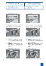
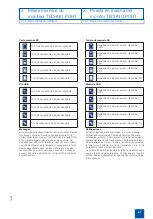
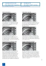
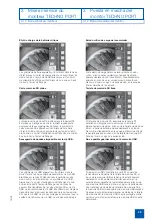
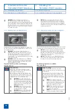
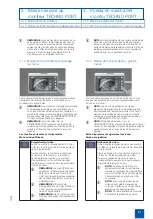
>6'%*012146/QPKVQTGTOÒINKEJVFGP#PUEJNWUU\YGK
-
GT%/158KFGQGKPJGKVGPOKV.GOQUVGEMGT#WHFGT)GTÀVG
4ØEMUGKVGPGDGPFGO0GV\VGKNCPUEJNWUUDGHKPFGVUKEJFKG
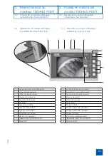
Anschlussbuchse
9
HØTFKGRTKOÀTG%/158KFGQGKPJGKV
6%#/QFGT8+&'1'0&15-12
8
Der Anschluss
8
HØTFKG\YGKVG%/158KFGQGKPJGKVDGHKPFGV
UKEJCPFGTNKPMGP)GJÀWUGUGKVGKOQDGTGP$GTGKEJ
1
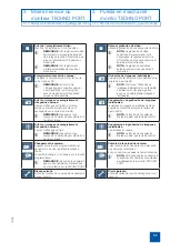
HINWEIS:
An beiden Anschlüssen kann das
VIDEOENDOSKOP (Artikel: 81251001-465) oder
die T-CAM (Artikel: 80407 CA) von KARL STORZ
angeschlossen werden. Videoeinheiten anderer
Hersteller können nicht angeschlossen werden.
1
HINWEIS:
Sind zwei Kameras angeschlossen, muss
der Anwender die Kamera, deren Bild angezeigt wer-
den soll, im Menü auswählen (siehe Kap. Betriebs-
modi und Menüführung).
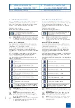
3. 11 Einschalten des Monitors
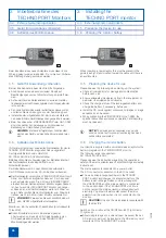
Den Monitor durch Drücken des Netzschaltzers
2
einschal-
VGPFKGITØPG0GV\MQPVTQNN.GWEJVG
1
leuchtet).
#PUEJNWUURTKOÀTG-COGTCWPFUGMWPFÀTG
%QPPGEVKQPQHRTKOCT[ECOGTCCPF
-COGTC
UGEQPFCT[ECOGTC
'KPUEJCNVGPFGU/QPKVQTU
5YKVEJKPIQPVJGOQPKVQT
3 Inbetriebnahme des
3 Installing the
6'%*012146/QPKVQTU
6'%*012146OQPKVQT
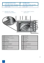
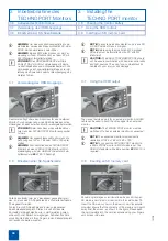
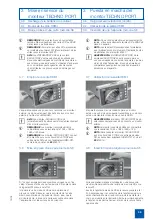
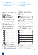
3. 10 Connection of primary camera and
secondary camera
9
6JG6'%*012146OQPKVQTGPCDNGUVYQ%/15XKFGQ
WPKVUVQDGEQPPGEVGFYKVJ.GOQEQPPGEVQTU1PVJGTGCT
of the device, next to the power supply connection, there
is a connection socket
9
HQTVJGRTKOCT[%/15XKFGQWPKV
6%#/QT8+&'15%12'
8
The connection
8
HQTVJGUGEQPF%/15XKFGQWPKVKU
located on the top left-hand side of the housing.
1
NOTE:
The VIDEOSCOPE (Article: 81251001-465)
or T-CAM (Article: 80407 CA) from KARL STORZ can
be connected at both connections. Video units from
other manufacturers cannot be connected.
1
NOTE:
If two cameras are connected, the user must
select the camera for which the images are to be
displayed in the menu (see chapter Operating modes
and menu navigation).
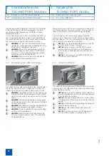
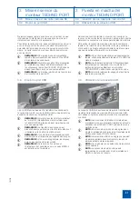
3. 11
5YKVEJKPIQPVJGOQPKVQT
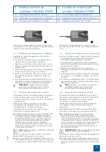
5YKVEJQPVJGOQPKVQTD[RTGUUKPIVJGRQYGTUYKVEJ
2
(the green pilot lamp
1
lights up).

