206
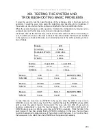
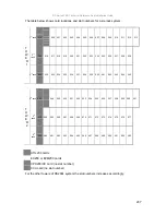
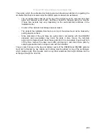
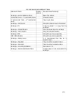
If anything is ever observed that does not agree with the table and notes above, then
probably there is a problem in the system. If the upper LED of one of the EX200 modules is
not on, then this may indicate that there is a short circuit in the line cables that have been
connected to that module. In such a case, the cable is supposed to be checked for any short
circuit.
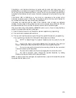
If the FAULT LED on SPS200 is on, then there is a component in the system, which
consumes excessive power. In that case, the system must be shut down and checked for
any mistakes that may have been made during installation.
If problems are observed with the LEDs of the CPU200, CCU, UTIL200 and SPS248
modules, then the power to the system must be cut, the modules whose LEDs are off must
be replaced with new ones, and then the system must be put into operation again.
If the lower LED of any of the EX200 or EVM200L cards is not on, then it is likely that there
would be a problem with that card. In that case:
1) Power to that card must be cut through the operator telephone by programming,
2) The card must be replaced with a new one,
3) The new card must be powered, again, through the operator telephone by programming.
The programming procedure to be followed for that purpose is as follows:
a)
877777 is dialed through the operator telephone and one waits for the dial
tone,
b)
Power to the card is cut by dialing 800950, then slot number of the card and
finally 0. At that point, either the dial tone or the error tone would be received.
c)
The card is removed from its slot by disconnecting it from the line connection
card and it is taken out of the system.
d)
The new card is placed into the slot by plugging the line connection card.
e)
The card is powered, again, through the operator telephone, by dialing
800950, then the slot number of the card and finally 1.
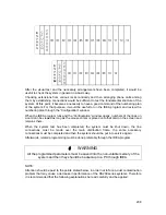
NOTE: In order to power the card again, as explained above, a period of at least 30 seconds
must pass after the power is cut.
Содержание DS200
Страница 1: ...11 2010 TECHNICAL REFERENCE AND INSTALLATION GUIDE PBX DS SERIES...
Страница 2: ...DS SERIES PBX TECHNICAL REFERENCE AND INSTALLATION GUIDE NOVEMBER 2010...
Страница 17: ...DS Series PBX Technical Reference And Installation Guide 7...
Страница 69: ...DS Series PBX Technical Reference And Installation Guide 59...
Страница 80: ...70...
Страница 94: ...84 Type 4 Type 5 According to its position See the diagrams above for each type Upper PABX Lower PABX...
Страница 222: ...11 2010...


