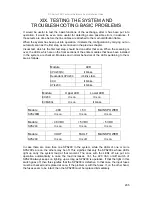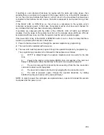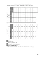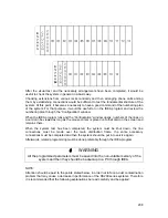
200
XVIII.1.D. CABINET-TYPE SYSTEMS WITH TWO
CABINETS
1) One makes sure the intra-rack, inter-rack and inter-cabinet connections have been
made properly.
2) The primary mains switches that are on the control panels of the cabinets are
checked to see whether they are off.
3) The primary battery switches that are on the control panels of the cabinets are
checked to see whether they are off.
4) The mains and battery switches on the entire SPS200 modules are checked to see
whether they are off.
5) The mains cables of the entire SPS200 modules are connected to the mains outlets
that are on the control panels of the cabinets.
6) The mains cords coming from the mains outlets that are on the control panels of the
cabinets are plugged into outlets of the premise that have been grounded correctly.
Since the primary mains switch is protected by a 10 A fuse, mains outlet of the
building is supposed to be protected by a fuse with higher rating.
7) The batteries (if battery connection is to be made) are connected to the battery
connection leads that are on the first cabinet.
8) The connection from the battery switch to the first of the SPS200 battery connectors
is made. (Keep in mind that the battery connection is made for a single cabinet and it
is not made to all SPS200 modules.)
9) The entire mains switches on the SPS200 modules are turned on, beginning with the
SPS200 module in the first rack.
10) The battery switch is turned on, which is on the SPS200 module to which the
batteries have been connected.
11) The primary mains switch that is on the control panel of the second cabinet is turned
on.
12) The primary mains switch that is on the control panel of the first cabinet is turned on.
13) The primary battery switch that is on the control panel of the first cabinet is turned on.
14) The fan switches that are on the control panels of the cabinets are turned on. The
fans must be working while the system is operating.
After being powered, the system carries out a series of automatic tests in order to check the
current configuration. Beginning with the card that is in the rightmost slot, two LEDs that are
on the front plastic panel of each card start to light up in a row. This action begins with the
bottom rack.
After the entire LEDs have started to light up, the message “connecting” appears on the LCD
screen of the LT200 (-H) or FT20 feature telephone set that has been connected to the
system. Once that message disappears, the system is ready to operate.
Содержание DS200
Страница 1: ...11 2010 TECHNICAL REFERENCE AND INSTALLATION GUIDE PBX DS SERIES...
Страница 2: ...DS SERIES PBX TECHNICAL REFERENCE AND INSTALLATION GUIDE NOVEMBER 2010...
Страница 17: ...DS Series PBX Technical Reference And Installation Guide 7...
Страница 69: ...DS Series PBX Technical Reference And Installation Guide 59...
Страница 80: ...70...
Страница 94: ...84 Type 4 Type 5 According to its position See the diagrams above for each type Upper PABX Lower PABX...
Страница 222: ...11 2010...


