during interference. Next, touch the STORE key. While the
STORE key is depressed, an audible beep sounds and “SET”
flashes momentarily on the LCD display above the STORE key.
Those stick, potentiometer and switch positions are now stored in
the transmitter’s memory circuits, to be sent to the receiver’s
memory automatically.
To verify the input of the fail-safe preset positions, turn the trans-
mitter “off” while leaving the receiver’s power “on.” Observe the
reactions of the servos. They should assume the positions that
you entered with the STORE key.
Note: These preset positions remain stored in the transmitter’s
memory until both the transmitter battery pack and the lithium
back-up battery have been removed (or until Code 28, Data
Reset, has been performed). Therefore, you do not have to reset
each time you fly. Should you wish to adjust the fail-safe preset
positions, simply access the Fail-Safe function once again and
adjust the preset as you have just done. The transmitter automati-
cally recalls the settings for the last fail-safe adjustment.
The fail-safe in the SPCM offers three types of fail-safe: Hold,
fail-safe presets, or a combination of the first two.
SPCM Hold
The Hold feature is automatically activated when the radio is
turned “on” and in the SPCM modulation.
This feature stops (or holds) the servos in the positions that they
were in just prior to the interference. When a clear signal is
restored, the Hold function releases and control of the airplane
returns you.
SPCM Fail-Safe
Once the Fail-Safe function has been activated by signal interrup-
tion (interference), the receiver automatically moves the servos to
a preset position. You determine the pre-determined servo posi-
tions. In the SPCM Fail-Safe, the time delay (the amount of time
it takes, starting the moment the interference occurs, until the ser-
vos assume the preset positions) is fixed at .25 or 1/4 second.
After the interference has ceased, normal operation of the air-
plane returns to you immediately.
Note: Auxiliary channels 4 and 5 cannot be preset for fail-safe
positions. These channels (9 and 10, respectively, on the receiver)
hold the position of their last good signal from the transmitter.
To select the servos that will return to the preset positions, access
Code 77 as instructed earlier. Press the numerical keys corre-
sponding to channels 1-8 on the receiver. (Refer to Section 3.1,
Channel Assignment, to determine functions correlating to chan-
nel numbers.)
When the STORE key is depressed, an audible beep sounds and
SET flashes momentarily on the LCD display above the STORE
key. The stick and switch positions are now stored in the trans-
mitter’s memory circuits, to be sent to the receiver’s memory
automatically.
To verify the input of the fail-safe preset positions, turn the trans-
mitter “off” while leaving the receiver’s power on. Observe the
reactions of the servos. They should assume the positions that
you entered with the STORE key.
Note: These preset positions remain stored in the transmitter’s
memory until both the transmitter battery pack and the lithium
back-up battery have been removed (or until Code 28, Data
Reset, has been performed). Therefore, you do not have to reset
the fail-safe each time you fly. Should you want to adjust the fail-
safe preset positions, simply access the Fail-Safe function once
again and adjust the presets as you have just done. The transmit-
ter automatically recalls the settings for the latest fail-safe
adjustment.
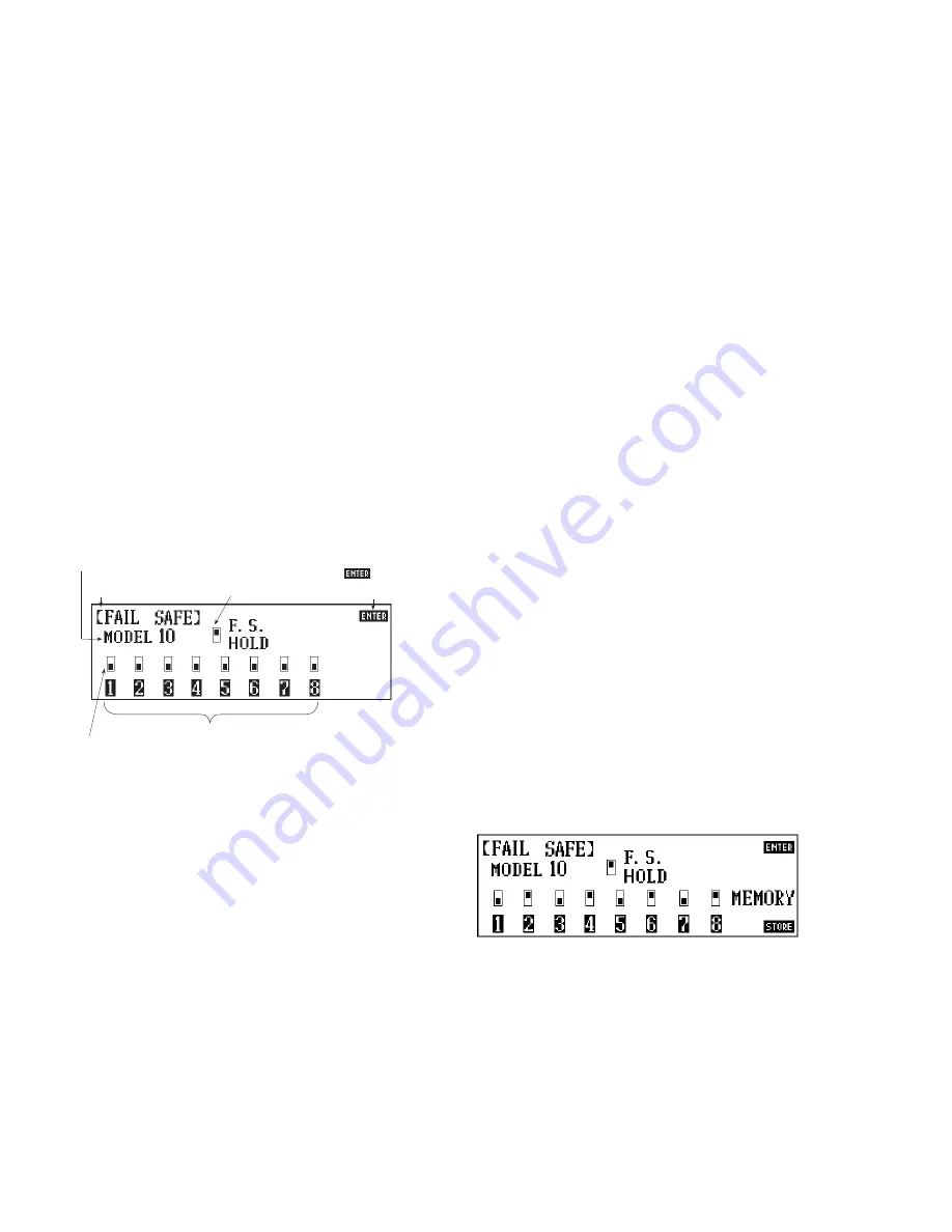
Combination Fail-Safe and Hold (S PCM)
The 10X also allows you to combine the Hold and Fail-Safe pre-
sets for the first eight (8) channels on the receiver—you can
select Fail-Safe or Hold independently for channels 1-8 on the
aircraft. In other words, some channels will hold their last clear
signal position, while others assume a preset position.
For example, if you want channels 1, 3, 5 and 7 to maintain a
hold position, while channels 2, 4, 6 and 8 assume a preset posi-
tion, touch the numbers 2, 4, 6 and 8 on the fail-safe screen. The
LCD should read as follows:
Note: Channels 1, 3, 5 and 7 were not touched (as is exhibited
by the location of the shaded boxes corresponding to the channel
numbers) and automatically hold their last clear signal.
56
10X MANUAL Airplane
Indicates feature
being accessed
Indicates model number
for which feature is being
accessed
If upper area is shaded, channel will
assume preset; if lower area is shaded,
channel will assume HOLD
1–8 correspond to channel numbers on receiver
Indicates whether
channel is in FAIL-SAFE
or HOLD position
Touch to
memorize data
and exit program


