switch to those trim settings when that particular Flight Mode is
selected. Also note that the trim setting for each Flight Mode is
displayed on the info screen when each Flight Mode is selected.
Note: It’s important to remember that when FM Trim is acti-
vated, any trim changes made affect only the Flight Mode that
you are presently in and will have no affect on the trim in any
other flight.
When FM Trim is inhibited, the digital trim positions affect all
Flight Modes and changes made in any Flight Mode will affect
all other Flight Modes.
Flight Mode Switch Position
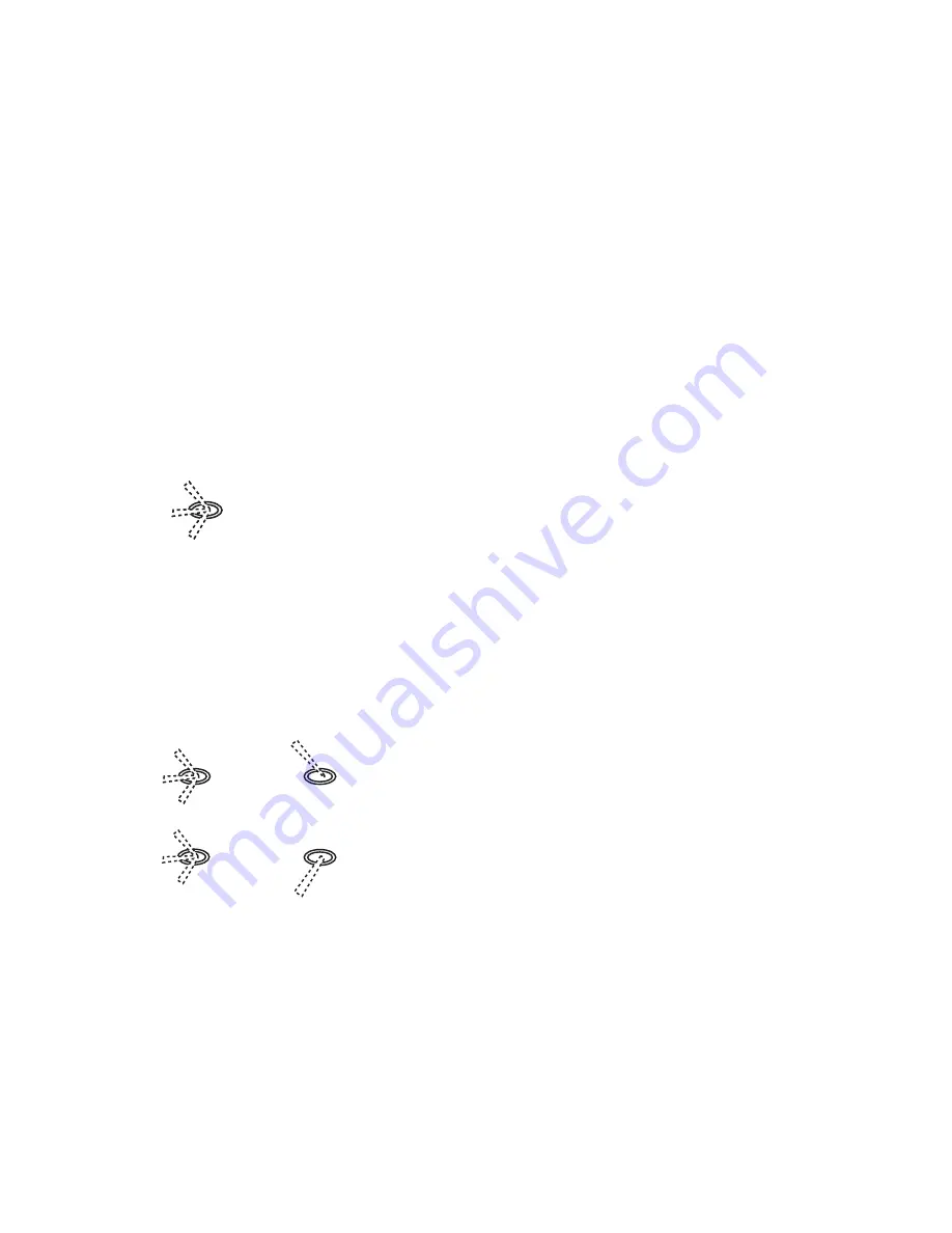
As illustrated above, the flight modes can be located in one of
three positions, the aileron, elevator or the rudder dual rate
switches. When a switch is selected, the other two switches are
turned off and have no effect.
When only three flight modes are selected, programming the
extra to INH causes the flight modes to function as follows:
To activate Flight Modes 3 and 4, touch ACT below EXTRA in
the flight mode screen.
Now, the mix switch, located on the back right of the transmitter,
allows you to access Flight Mode 3 or 4 when it’s flipped in the
forward position.
When EXTRA is activated, the above switch positioning allows
you to access five flight modes.
Note: When the selected flight mode switch is in the upper, or
away, position, Flight Mode 0 is always activated regardless of
the position of the mix switch. It’s recommended that Flight Mode
0 be used as a standard “safe setting” (we call it home base) so
that in case of an emergency (flame out), returning this switch to
the 0 position will deactivate any unusual setting, making for an
easy dead stick landing.
Utilizing Flight Modes
It is highly recommended that all pilots, regardless of their prior
experience, take the time to become familiar with programming
and using the system’s individual functions and controls before
proceeding with the more advanced Flight Mode feature.
The pilot should first program and fly the aircraft using basic
functions. These initial flights will be very useful in trimming the
aircraft, identifying its flight characteristics, and becoming famil-
iar with the 10X programming, functions, and operation. The
pilot can then proceed with programming other individual func-
tions until the desired functions are operating satisfactorily. After
this is accomplished, the pilot may, at his discretion, confidently
proceed with programming and implementing the Flight Mode
feature where individual functions are combined to form Flight
Modes.
To assist you in obtaining the greatest possible benefit from the
JR 10X Flight Mode feature, we have developed a procedure to
guide you through programming Flight Modes. The procedure is
straightforward, practical, and will allow you to program Flight
Mode settings in a very safe, deliberate, and controlled fashion.
Flight Modes
What is a Flight Mode? A Flight Mode represents an aircraft con-
figuration that is designed or optimized to assist the pilot and the
aircraft in performing a specific flight task, or group of tasks.
Examples of flight tasks include, but are certainly not limited to,
the following: takeoff, landing, normal-speed maneuvering, high-
speed maneuvering, snap rolling, slow-flight maneuvering, spot
landing, smooth and graceful maneuvering, 3-D maneuvering,
and a host of others that are defined by the variety of aircraft,
accessories, and flying styles that exist in today’s R/C hobby.
The objective of programming Flight Modes is to setup each
Flight Mode (switch position) to provide an ideal aircraft config-
uration for performing a particular flight task(s). It has the effect
of reducing the pilot’s workload and optimizing the aircraft’s per-
formance in the flight envelope that is typically associated with
the task (e.g., landing usually involves slow flight and maybe
extended gear, lowered flaps, and other things that result in a
high-drag airframe).
For instance, the pilot decides to use Flight Mode number 0
(FM-0) for landing. Switching to FM-0 on the transmitter lowers
the landing gear, lowers the flaps, adds elevator and aileron trim
to compensate for flap deployment, and selects the appropriate
control throws to be effective at low landing speed. All of this
(and more!) can be accomplished by flipping one switch to select
FM-0. This represents a substantial reduction in the Pilot’s work-
load and risk to the aircraft when compared to flipping multiple
switches to the correct positions. The pilot’s workload is further
reduced by the fact that control rates/curves and other settings are
selected to provide for optimum maneuvering at low landing
speeds in the landing configuration.
20
10X MANUAL Airplane
Selected flight mode switch
F/M 0
F/M 1
F/M 2
When only flight mode 0, 1, 2 are activated
Selected flight mode switch
F/M 0
F/M 1
F/M 2
F/M 0
F/M 3
F/M 4
Mix Switch
Forward
position
Rear
position


