described below uses a programmable mix and the GEAR chan-
nel (channel 5) to mix the GEAR channel to itself.
Note: It is assumed that Flight Modes are already active, the
pilot has identified a Flight Mode(s) to be used for takeoff and
landing, and the D/R&EXP settings have been established as
described above. It is also assumed that a Retract Servo is used
to control the landing gear operation and the retract linkages
have been adjusted for proper operation.
1. Make sure that the GEAR switch is active in the Function
Select feature (Code 17).
2. Select an unused Program Mix (Codes 51-55). Enter “5” as
the master and “5” as the slave, mixing the GEAR channel to
itself. Touch ENTER to obtain the next Program Mix screen.
3. Pull the Retract Switch toward you and leave it in this posi-
tion.
4. Touch STORE. (A negative percentage will appear under
OFFSET. This value will typically be –85%.)
5. Touch PAGE to advance to the switch/position selection
screen. Set the Flight Modes (FM-0 – FM4) that you will use
for takeoff and landing (gear down) to POS-1. All other FMs
and switches should indicate POS-0.
6. Touch PAGE twice to get back to the first Program Mix
screen.
7. Position the Flight Mode switch to select a Flight Mode that
will have the gear retracted (gear up). POS-0 should appear
over the “0” percentages at the right of the screen.
8. Touch + until the percentage reads approximately 50% (any-
thing over 30% usually works).
9. Touch ENTER to exit the Program Mix function and go to the
Function Select feature (Code 17).
10. Inhibit the GEAR switch in Code 17, and then touch ENTER
to exit Function Select.
11. Try the Flight Mode switch (not the retract switch) to see if
the retracts work. If they work properly you are finished. If
they do not work at all, proceed to the next step. If they work,
but move in the wrong direction, go to Step 13 below.
12. If the retracts do not work at all, access the Program Mix (51-
55) that was used in Step 2 above. Position the Flight Mode
switch so that POS-0 appears over the percentage (50%).
Touch TURN to change the percentage to “-”. Now check
retract operation again. If the retracts operate properly you are
finished.
13. If the retracts work with the Flight Mode switch but move in
the wrong direction, access the Program Mix (51-55) that was
used in Step 3 above and touch PAGE to advance to the
switch/position selection screen.
Now “swap” the POS-0 and POS-1 settings for FM-0 – FM-4
(change all POS-1s to POS-0s and all POS-0s to POS-1s). Leave
all other switches set to POS-0. The retracts should now operate
correctly with the Flight Mode switch.
Flaps
If your aircraft is equipped with flaps or you’re using the
Flaperon feature and would like flap operation to be controlled as
part of one or more Flight Modes, follow the steps outlined
below.
Note: It is assumed that Flight Modes are already active and
the D/R&EXP settings have been established. It also assumes
that a flap servo(s) (or left aileron servo if Flaperon is active) is
plugged into the Flap or AUX 1 channel of the receiver.
1.The Flap System description (Code 66) recommends inhibiting
the Flap Lever in the Function Select feature (Code 17). So
bring-up the Function Select feature (Code 17) and be sure that
the Flap Lever on the first page of the display is inhibited.
2.Bring up the Flap System function (Code 66). With the trans-
mitter and receiver turned-on, put the Flap Switch in the Mid
position and touch + or - to set the flap throw in the Mid posi-
tion. Then move the switch to the Land position and touch
+ or - keys to set the flap throw in this position.
If you already know the direction and approximate amount of
elevator input that will be required to counteract pitch changes
caused by lowering the flaps, enter elevator values at this time
in the same fashion as was done for the flap throws.
3.Test-fly the aircraft and use the Flap switch to deploy the flaps
at a safe altitude. Use the Flap System function (Code 66) to
adjust the flap and elevator settings to obtain the desired flight
characteristics for both the Mid and Land settings. Once you’re
comfortable with flap performance, proceed with the next step
to assign the Flap System to Flight Modes. Don’t worry if
deploying the flaps causes the aircraft to roll or yaw, or other-
wise be out of trim. This can be taken care of using the digital
trims with Flight Mode Trim, Code 17 activated.
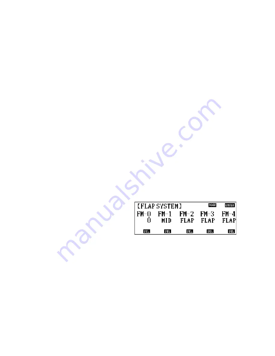
4.Bring up the Flap System function (Code 66) and touch PAGE
to obtain the second screen of the display. Assign flap opera-
tion to each Flight Mode (FM-0 – FM-4) as described in the
Code 66 function.
• Assigning a 0 to a Flight Mode inhibits flap operation for the
Flight Mode. (Flaps cannot be deployed when this FM is
selected, not even with the Flap switch).
• Assigning “FLAP” to a Flight Mode allows the pilot to use the
Flap Switch to control flap deployment (MID and LAND)
when the Flight Mode is selected. The flaps will be controlled
in the same fashion as when the aircraft was test-flown in Step
3 above.
• Assigning “MID” to a Flight Mode will result in the flaps low-
ering to the Mid position whenever the Flight Mode is select-
ed. The Flap switch is inhibited when this Flight Mode is
selected.
22
10X MANUAL Airplane


