background image

Gyro Gain Sensitivity System

The 10X features a sophisticated gyro gain sensitivity system that
allows in-flight control of gyro gain for two separate gyros. It
provides for standard gain adjustments (fixed gains), as well as
Stick Priority Gyro Gain adjustment where gyro gain is progres-
sively reduced as the stick is moved further off center. Stick  pri-
ority if highly advantageous for controlling gyros in aerobatic air-
craft.

Up to two gyros may be used to control two of the three primary
flight controls (elevator, rudder or aileron). Typical aerobatic
applications involve gyros on the rudder and/or elevator. Each
gyro can have three different gains that are selectable via Flight
Modes or the AUX 2 switch. The gains can be fixed or variable
using the Stick Priority Gyro Gain feature.

Note: This function is designed to be used only with gyros that

have in-flight proportional gain adjustment capability, such as
JR’s NEJ-900, and NEJ-3000 Piezo gyros. Single and dual rate
gyros that use a potentiometer to adjust the gain will not work
properly with this function.

Connections

Plug the gain connector of the first gyro into the AUX2 port of
the receiver. Plug the gain connector of the second gyro into the
AUX3 of the receiver. If only one gyro is to be used, connect its
gain to AUX2. If two gyros are to be used, be mindful of which
control (rudder, elevator or aileron) is to be controlled by AUX 2
and which is to be controlled by AUX3 as you will need to know
this later if Stick Priority Gyro Gain is achieved.

Note: Since the gain for the second gyro must be plugged into

AUX3, it precludes using the Dual Elevator feature in Wing Type
(Code 22) because dual elevator also uses AUX3. If the aircraft
uses two elevator servos and you would also like to use two
gyros, the two elevator servos must be connected through a
Y-harness.

Accessing Standard Gyro Gain Sensitivity

To access the standard gyro gain sensitivity feature (no stick pri-
ority), enter Code 44 in the code number access selection or use
the direct mode method. 

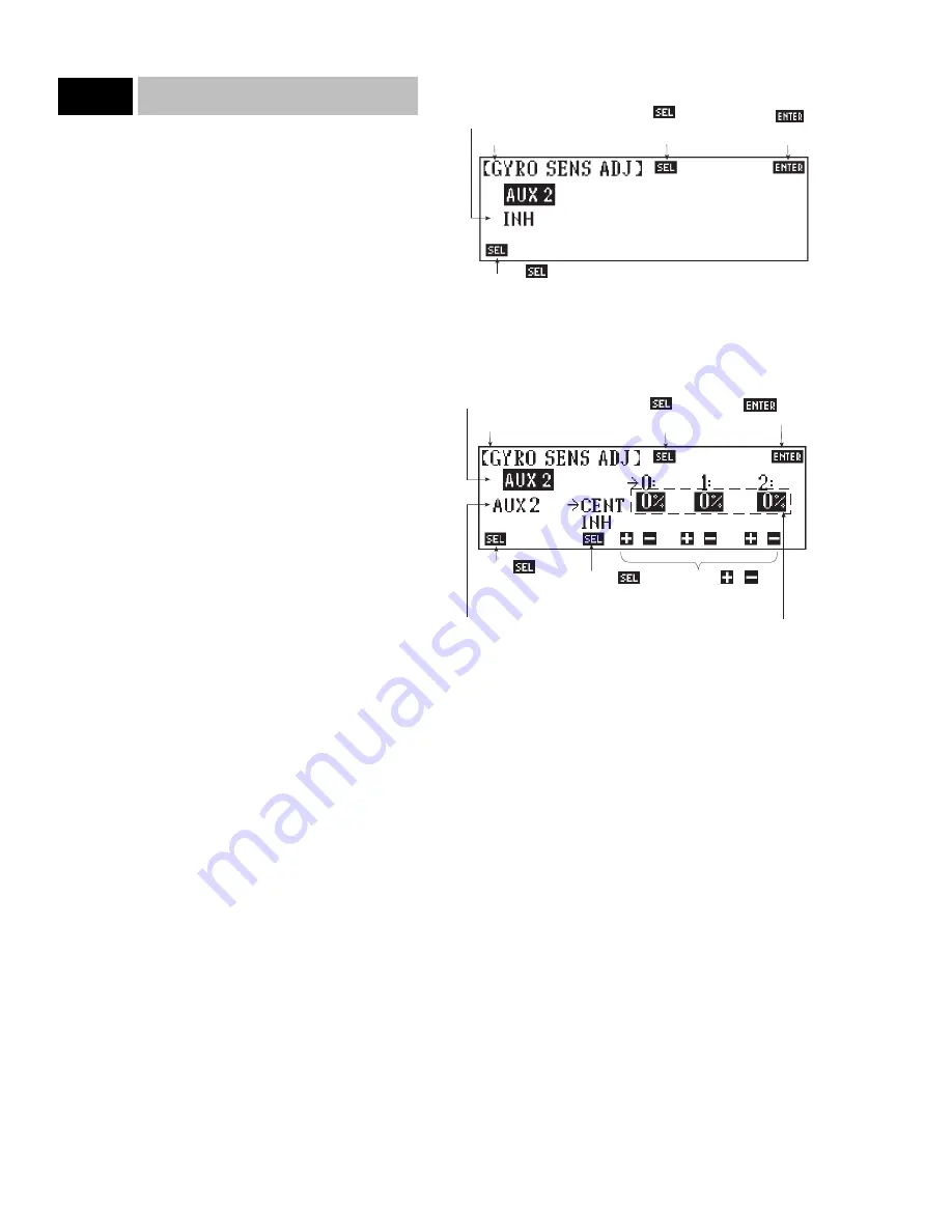
The screen will appear as follows:

1. Touch the lower left SEL to activate the gyro sensitivity system

and to obtain the following display:

2. Touch SEL at the top of the display until AUX2 is displayed

and highlighted as shown. This indicates that the display is
ready to accept gyro gain values for the gyro plugged into the
AUX2 channel.

3. Touch SEL at the lower left of the screen until AUX2 appears

under the highlighted AUX2. This indicates that the AUX2
switch will be used (at least for now) to select which gain posi-
tion is to be programmed.

Setting the Gain Percentages

In our example on the following page we have se the first position
(Position 0)  gain to 0%. This provides the ability to turn the gyro
off in flight when this position is selected. Position 1 has been set
to a moderate amount of gain (30%) and Position 2 has been set
to a high percentage of gain (70%). We suggest that you program
your system in the same manner until you become familiar with
how everything works, then you can experiment on your own.
(Note: The percentages will vary according to the instructions
that come with the gyro and the particular model being flown.)

38

10X MANUAL  Airplane

8.12

Code 44

Indicates AUX2 is selected

Touch          to activate the Gyro Sensitivity
function

Touch
to exit function

Touch          to toggle
between AUX2 and
AUX3 to set gains

Indicates function being
programmed

Touch          to select
AUX2 switch or Flight
Modes to activate gyro
gains in flight

Touch          to toggle
between AUX2 and
AUX3 to set gains

Touch          to toggle
between standard gyro
gain and Stick Priority
gyro gain

Touch      or       to
increase or decrease
gyro gain settings

Indicates gyro gain
settings for each
position (0, 1, 2)

Indicates AUX2 switch is
being used to select
positions for programming

Indicates AUX2 is selected

Indicates function being
programmed

Touch              to save
programming and exit
function

Содержание 10X HELICOPTER VERSION

Страница 1: ...U S E R M A N U A L A I R P L A N E V E R S I O N...

Страница 2: ...Programmable Mixing 46 8 15 Code 62 Aileron to Rudder Mixing 49 8 16 Code 63 Elevator to Flap Mixing 50 8 17 Code 64 Rudder to Aileron Elevator Mixing 51 8 18 Code 66 Flap System 53 8 19 Code 75 Servo...

Страница 3: ...these channels to be used as slave channels during mixing and making it so the primary control knob lever or switch will have no effect Code 17 A dual elevator feature is pre programmed in Code 22 and...

Страница 4: ...ty JRDigitalServos With the development of the new JR Digital Servos JR has set the new standard in servo technology a technology that has remained virtually unchanged for the past 25 years Using a sp...

Страница 5: ...cks Servo NES 8231 Digital Torque oz in 88 oz in Speed S 60 22 Input Pulse 1 5 ms 600 s Power Source 4 8 6 0 volts Motor Coreless Weight oz 1 73 oz Size W L H 75 x 1 54 x 1 36 Component Specification...

Страница 6: ...d Active Antenna An optional base loaded active antenna is available for use with the PCM10X transmitter It is considerably shorter than the stan dard antenna but cannot be collapsed for storage in th...

Страница 7: ...nsmitter that enables you to connect a neck strap JRPA023 This hook has been positioned such that your transmitter will have the proper balance when the antenna is extended The 10X allows you to indiv...

Страница 8: ...n module system for transmitter frequency and band changes If you wish to change a frequency you can simply change the radio s module commonly referred to as either an RF module or transmitter module...

Страница 9: ...vide the proper security as well as the proper vibration isolation for your servo 3 The servo arm must be able to move freely over its entire range of travel Make sure that the control linkages do not...

Страница 10: ...times Notes pertaining to the battery alarm 1 The word Battery will only flash if you are in the initial display screen If you are in any other screen you will only hear the beeping of the alarm If yo...

Страница 11: ...g the Info function highlights the chosen function Next press the ENTER key to bring up the function After making the necessary adjustments press the ENTER key once again This will bring you back to t...

Страница 12: ...e center and end values in the screen The capability for using 2 gyros with independent adjustments is available in this function Note A remotely adjustable gyro must be used 51 55 PGM MIX Programmabl...

Страница 13: ...election or by using the direct mode method The screen will appear as follows To reverse the travel direction of any servo channel simply touch the number that correlates to that channel Note that the...

Страница 14: ...ault set tings the 10X is set to simultaneously adjust both direction indi cated by the shaded area covers both direction values and an S appears in the shaded box at the top of the screen see above s...

Страница 15: ...l This provides the pilot with very smooth precise control while using relatively large movements with the control sticks If you d like to try Expo for the first time a value of 20 is a good place to...

Страница 16: ...sponse rate of this servo is greater around neutral and decreases as the stick reaches its travel limits This negative exponential rate is useful if the control is very slow or unre sponsive around th...

Страница 17: ...r quad flap mode the aileron trace rate will affect both servos Accessing and Utilizing the Trace Rate Function To access the Trace Rate function enter Code 14 in the code number access selection or u...

Страница 18: ...ow effect Press the or key to increase the amount of sub trim To reset the sub trims to the factory default of 0 press the and keys simultaneously or press the CL key After adjusting the sub trims for...

Страница 19: ...ate the flight modes and to assign the flight modes to one of three switch locations These switch locations include the aileron D R switch the eleva tor D R switch or the rudder D R switch Flight Mode...

Страница 20: ...complished the pilot may at his discretion confidently proceed with programming and implementing the Flight Mode feature where individual functions are combined to form Flight Modes To assist you in o...

Страница 21: ...st be addressed first Take some time to become familiar with the explanations of the Flight Mode switches in Code 17 Pay particular attention to the note regarding the FM 0 or home base position and u...

Страница 22: ...et to POS 0 The retracts should now operate correctly with the Flight Mode switch Flaps If your aircraft is equipped with flaps or you re using the Flaperon feature and would like flap operation to be...

Страница 23: ...ustment feature such as that found in JR s NEJ 900 1 Plug the gyro into the AUX 2 port of the receiver and follow the directions provided with the gyro for other connections 2 Access the Gyro Function...

Страница 24: ...are two or more Flight Modes that have the same direction RU RD etc and you wish to have different throws percentages associated with this direction proceed with Step 5 below If you want the same thro...

Страница 25: ...witch position display Identify a Flight Mode that is not used for takeoff or landing Touch SEL under this flight mode to indicate that it will use POS1 Leave all other switches set to POS0 Now mixing...

Страница 26: ...r to be able to turn mix ing off either POS0 or POS1 values must be set to zero Trimmer Function Flap The flap lever when active raises or lowers the flaps in unison with one another To activate the f...

Страница 27: ...positions and each point can be moved to any position from 0 to 100 Adding New Points Any time STORE appears on the bottom of the LCD you can add a new point on the curve Move the throttle stick and n...

Страница 28: ...touch the PAGE key Flip the switch selected to select POS 0 or POS 1 in order to make adjustments to the desired throttle curve Note Position 1 has priority over Position 0 such that if a switch or f...

Страница 29: ...Check to make sure that the servos move in the proper direc tion For a right turn the right aileron should raise while the left aileron lowers simultaneously For a left turn the opposite is true the...

Страница 30: ...the direction of the aileron dif ferential while still retaining the differential percentage value Your LCD confirms the negative value by replacing the below the dif rate with a symbol If you want to...

Страница 31: ...To adjust the wing differential and switch positions refer to the wing differential feature section on the previous page Note The V tail mixing and dual tail selection is automatically inhibited in t...

Страница 32: ...direction for both elevator and rudder inputs If the servos are not mov ing in the proper manner direction use the Servo Reversing function Code 11 to reverse the travel direction of the servo s that...

Страница 33: ...e transmitter With the receiver and transmitter turned on examine the two servos and notice if the servo arms are at 90 or perpendicular to the vertical stabilizer Reinstall the arm if necessary to ac...

Страница 34: ...Note the value given is in degrees per second Touch the key to increase servo speed When the Flight Modes are active the corresponding flight mode will appear at the upper left hand corner of the scre...

Страница 35: ...iven model memory you will not be able to change your mind and recall the cleared information To clear all data from a given model simply touch the clear key The screen will ask ARE YOUR SURE YOU WANT...

Страница 36: ...utton is depressed etc Touch the SEL key until F Mode appears below ACT in Snap Roll function Code 31 Note Flight modes must be activated in Function Select Code 17 The screen will appear as illustrat...

Страница 37: ...the same direction will have another set of throws Proceed to Step 4 below 4 It s now time to set the throws percentages for the directions that have been established for each Flight Mode Touch PAGE t...

Страница 38: ...ing Standard Gyro Gain Sensitivity To access the standard gyro gain sensitivity feature no stick pri ority enter Code 44 in the code number access selection or use the direct mode method The screen wi...

Страница 39: ...ode to select the gain setting Position 0 1 2 for that Flight Mode When a position is selected it represents the position for both gyros if more than one gyro is being used For example if Position 0 i...

Страница 40: ...0 for both gyros as it will provide the ability to turn the gyro gain com pletely off in the event that the gyro becomes over sensitive 8 Put the AUX2 switch in the middle position Position 1 and not...

Страница 41: ...n access Code 12 Hold the control stick of the channel using the gyro to full left or up in case of elevator and reduce the travel adjust until the control surface begins to move Then hold full right...

Страница 42: ...ster channel You can also think of it as the controlled channel for the mixing feature For example you want to mix the aileron channel to the throttle channel Aileron is the Master or controlling chan...

Страница 43: ...th the mixing value to achieve the correct percentage and direction of mixing Touch the TURN key to reverse the direction of the mixing The mixing value remains the same and only the direction in the...

Страница 44: ...have no effect on the nose wheel steer ing There is one other very important feature associated with Origin Mix It is the ability to use a lever switch or knob to con trol other mixers even when the l...

Страница 45: ...ster channel is aileron elevator or rudder you have the option of allowing the Master channel s trim lever to mix into the Slave channel To activate trim mixing touch the SEL key The screen shows that...

Страница 46: ...ed channel The initial screen shows that the mixing feature is inhibited However after rudder is selected the screen will appear as fol lows Next choose the Slave channel by touching the corresponding...

Страница 47: ...usly you will reset the output value to 0 Stick Position This value is represented numerically just below the ENTER key and changes to show the current stick position You may find this useful when you...

Страница 48: ...im lever is also minute 48 10X MANUAL Airplane Multi Point Programmable Mixes The PCM 10XI aircraft system features 3 multi point pro grammable mixes Each of these programmable mixes allows up to 8 po...

Страница 49: ...ch choices are available E F ELEVATOR FLAP SWITCH UP POSITION M D ELEVATOR FLAP SWITCH MID POSITION L D ELEVATOR FLAP SWITCH DOWN POSITION MX MIX SWITCH AU AUX 2 UP POSITION GR GEAR SWITCH SNP SNAP RO...

Страница 50: ...the flaps are moving opposite to the direction that you want touch the TURN key This reverses the mixing direction giving you reverse throw while still retaining the mixing value To clear the flap per...

Страница 51: ...CL key or the or keys simul taneously To access the Rudder to Elevator screen press the PAGE key until the following screen appears Follow the same procedure used in Rudder to Aileron Mix to set valv...

Страница 52: ...eron mix value until no rolling coupling occurs Now roll left to knife edge and apply right rudder and note if the nose pitches up or down relative to the air craft Adjust the rudder to elevator mix v...

Страница 53: ...o redefine the servos center increasing travel adjust could over drive the flap servo Flight Mode Select The mid or land flap and elevator position can be programmed to automatically deploy in any of...

Страница 54: ...his has been completed access the Servo Test Function by entering Code 75 at the code number access selection or using the direct mode method Slow Servo Test The servos immediately begin to slowly cyc...

Страница 55: ...ceased control of the airplane returns immediately to you There are three time delays to choose from 25 sec 0 5 sec and 1 0 sec These time delays are the amount of time it takes starting the moment th...

Страница 56: ...To select the servos that will return to the preset positions access Code 77 as instructed earlier Press the numerical keys corre sponding to channels 1 8 on the receiver Refer to Section 3 1 Channel...

Страница 57: ...on the LCD display above the STORE key The switch positions and or stick positions are now stored in the transmitter s memory circuit to be sent automatically to the receiver s memory To verify the in...

Страница 58: ...If the slave radio is a computer radio 1 Select a model memory that s not being used and reset that memory to the factory default 2 Now set the modulation to PPM 3 Center all the trim levers aileron...

Страница 59: ...tter use the SEL key until the desired number letter appears then press the number letter It will appear in the indicated position Note The cursor automatically moves to the next entry posi tion To co...

Страница 60: ...elease the trim at the exact neutral if desired The pitch of the beep changes from right to left up to down right is a low pitched tone while left is a high pitched tone up is a low pitched tone and d...

Страница 61: ...more information Copy Function This Copy function allows you to transfer all data from the cur rent model to another model memory of your choice Note This function is only for use when copying models...

Страница 62: ...power switch to be turned off To exit the Modulation Selection function touch the ENTER key after selecting the proper modulation If you want to verify the modulation of your transmitter at any time s...

Страница 63: ...if applicable The 10X only trans mits the current model number and name as displayed Therefore if this is not the model you wish to transfer to the receiving radio access Code 84 Model Select to reca...

Страница 64: ...to you will be unable to call up the previous model memory for that model number Once you have chosen a receive to model memory touch the ST SP key to advance to the receive standby screen The screen...

Страница 65: ...m both systems and start the Data Transfer function again from the beginning Even if the counter display has decreased to 0 and faded out there is a safety indicator to detect an error in the receive...

Страница 66: ...rvals to 00 minutes 3 add seconds to the timer in ten 10 second increments up to 50 seconds Once the count down timer has been set to the proper time press the ENTER key to memorize the settings and e...

Страница 67: ...e The cursor automatically advances to the next position after a number is selected Touch the STORE key that appears after the first numerical selection to store the selected lock code in the 10X s me...

Страница 68: ...ads as they do not apply in this instance You must make certain that the center pin of your JR transmitter is always connected to the nega tive voltage for correct polarity hookup Note Please refer to...

Страница 69: ...dditionally your level of piloting competency must be high enough to ensure that you are able to control your aircraft under all conditions If you are a newcomer to radio control flying please seek he...

Страница 70: ...n to be closer by the appropriate air traffic control facility in the case of an airport for which a control zone has been designated or by the airport manager in the case of other airports e Do not h...

Страница 71: ...AL Airplane 71 Frequency Chart 14 Ch No Frequency 39 72 570 40 72 590 41 72 610 42 72 630 43 72 650 44 72 670 45 72 690 46 72 710 47 72 730 48 72 750 49 72 770 50 72 790 51 72 810 52 72 830 53 72 850...

Страница 72: ...turn your system installed in a model aircraft 3 Preferably use the original carton packaging molded foam container or equivalent to ship your system Do not use the system carton itself as a shipping...

Страница 73: ...DULATION 85 SPCM ZPCM PPM FM D R EXP POS L D R U L D R D TYPE AILE 0 ELEV RUDD AILE 1 ELEV RUDD AILE 2 ELEV RUDD AILE 3 ELEV RUDD AILE 4 ELEV RUDD Flight D R SW INH AILE ELEV RUDD Mode EXTRA INH ACT C...

Страница 74: ...Trace Rate 14 Flap System 66 FLAP ELEV Pos MID LND FM 0 FLAP 0 MID LND SW FM 1 FM 2 FM 3 FM 4 ELEV FLAP MIX 63 DN UP AUX2 AUX3 0 1 2 0 1 2 Center Stick Priority INH AIL ELE RUD INH AIL ELE RUD End FM...

Страница 75: ...MID FM2 LND FM3 MIX AXU AXD SNP GER 0 1 exp POS 0 1 OFF ACT Out In Out In L 1 2 3 4 5 6 H 0 0 100 100 INH ACT OFF ON INH ACT SW FM0 E F FM1 MID FM2 LND FM3 MIX AXU AXD SNP GER 0 1 exp POS 0 1 OFF ACT...

Страница 76: ...1999 Horizon Hobby Distributors Inc Distributed Exclusively by Horizon Hobby Distributors Champaign IL 61822 www horizonhobby com...

Отзывы: