Intesis
Box
®
KNX
– IR Universal AC
User's manual r1.0 eng
© Intesis Software S.L.U. - All rights reserved
This information is subject to change without notice
IntesisBox
®
is a registered trademark of Intesis Software SLU
URL
Email
tel
http://www.intesisbox.com
[email protected]
+34 938047134
9 / 48
Connection to IR and location
There is no special requirement to match the IR receiver and the IntesisBox IS-IR-KNX-1i interface. Simply
select your model from the list present in the plugin. If your AC unit is not present, please check the compatibility
list as in section 7. You can find more information about the IR configuration in section 5.
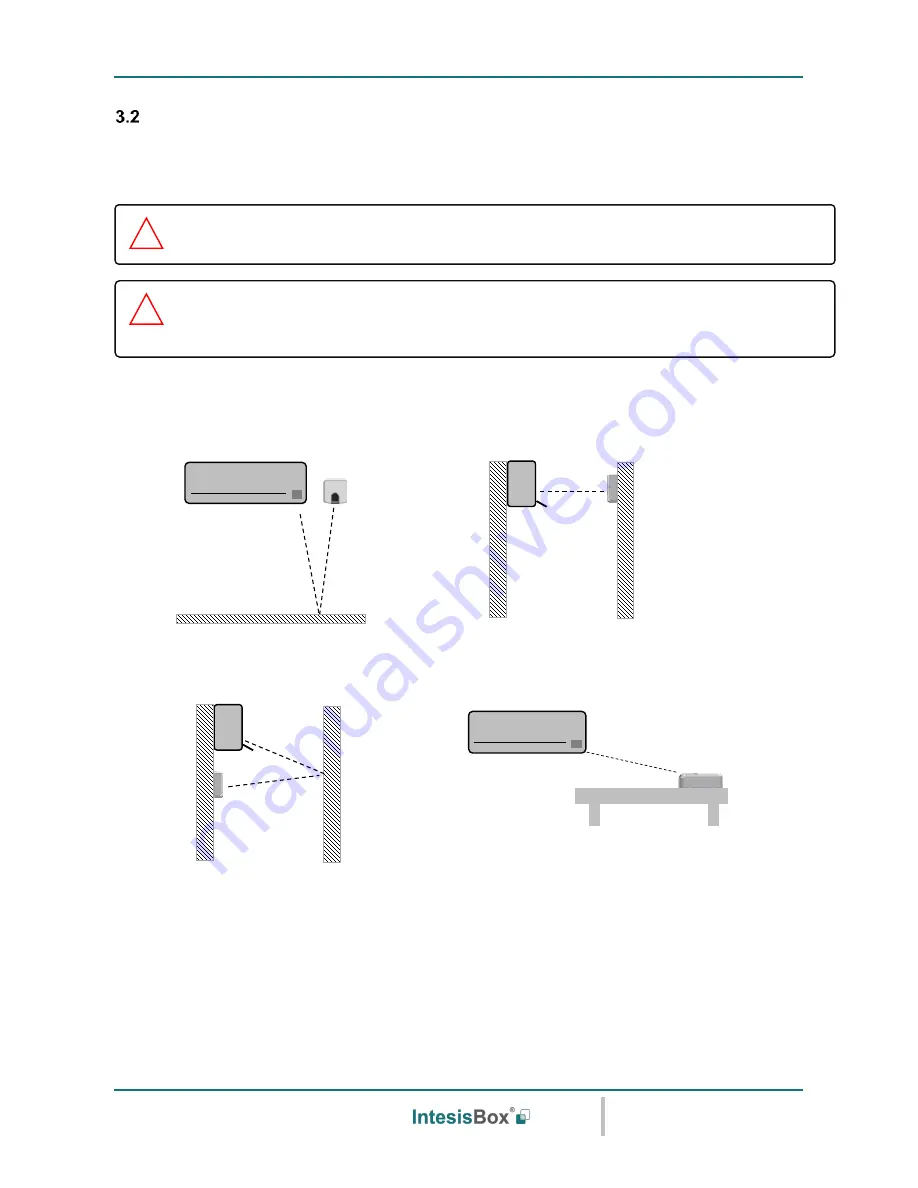
IntesisBox IS-IR-KNX-1i
can be installed in many different locations.
A) Side-by-side with the AC unit
B) In front of the AC unit
C) Under the AC unit
D) Desktop position
Figure 3.2
IR emitters and IR receiver location
Case A:
Installed side-by-side with the AC unit. In that case, the signal will travel from the IntesisBox device to
the AC unit tacking advantage of the rebounds on the floor or other furniture present in the room.
D
IMPORTANT:
Keep in mind that some furniture and materials (carpets, curtains, glass,
metal…) may affect on the IR communication.
!
NOTE:
The IntesisBox device has 2 IR emitters pointing at 2 different locations. Considering
this and IR reflections, valid locations for the IntesisBox device may be many and very different
depending on each installation. Check section 3.1 for more information.
!