LGA1366 Socket
16
Thermal/Mechanical Design Guide
2.2
Attachment to Motherboard
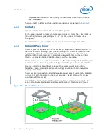
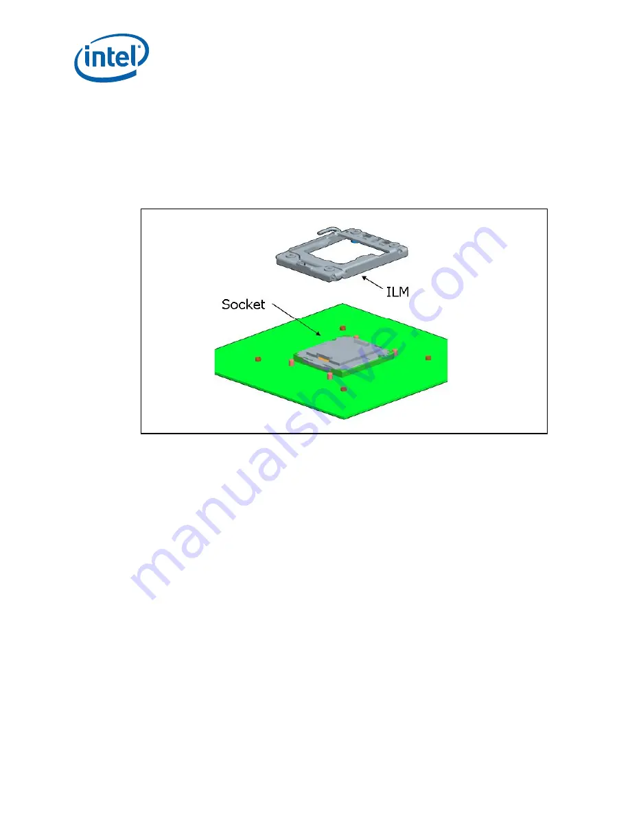
The socket is attached to the motherboard by 1366 solder balls. There are no additional
external methods (that is, screw, extra solder, adhesive, and so on) to attach the
socket.
As indicated in
Figure 2-4
, the Independent Loading Mechanism (ILM) is not present
during the attach (reflow) process.
2.3
Socket Components
The socket has two main components, the socket body and Pick and Place (PnP) cover,
and is delivered as a single integral assembly. Refer to
Appendix C
for detailed
drawings.
2.3.1
Socket Body Housing
The housing material is thermoplastic or equivalent with UL 94 V-0 flame rating capable
of withstanding 260 °C for 40 seconds (typical reflow/rework). The socket coefficient of
thermal expansion (in the XY plane), and creep properties, must be such that the
integrity of the socket is maintained for the conditions listed in the LGA1366 Socket
Validation Reports.
The color of the housing will be dark as compared to the solder balls to provide the
contrast needed for pick and place vision systems.
2.3.2
Solder Balls
A total of 1366 solder balls corresponding to the contacts are on the bottom of the
socket for surface mounting with the motherboard.
The socket has the following solder ball material:
• Lead free SAC (SnAgCu) solder alloy with a silver (Ag) content between 3% and
4% and a melting temperature of approximately 217 °C. The alloy must be
Figure 2-4.
Attachment to Motherboard
Содержание X5550 - Quad Core Xeon
Страница 8: ...8 Thermal Mechanical Design Guide ...
Страница 12: ...Introduction 12 Thermal Mechanical Design Guide ...
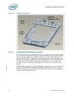
Страница 24: ...Independent Loading Mechanism ILM 24 Thermal Mechanical Design Guide Figure 3 3 ILM Assembly ...
Страница 26: ...Independent Loading Mechanism ILM 26 Thermal Mechanical Design Guide ...
Страница 48: ...Component Suppliers 48 Thermal Mechanical Design Guide ...
Страница 50: ...Mechanical Drawings 50 Thermal Mechanical Design Guide Figure B 1 Board Keepin Keepout Zones Sheet 1 of 4 ...
Страница 51: ...Thermal Mechanical Design Guide 51 Mechanical Drawings Figure B 2 Board Keepin Keepout Zones Sheet 2 of 4 ...
Страница 52: ...Mechanical Drawings 52 Thermal Mechanical Design Guide Figure B 3 Board Keepin Keepout Zones Sheet 3 of 4 ...
Страница 53: ...Thermal Mechanical Design Guide 53 Mechanical Drawings Figure B 4 Board Keepin Keepout Zones Sheet 4 of 4 ...
Страница 54: ...Mechanical Drawings 54 Thermal Mechanical Design Guide Figure B 5 1U Reference Heatsink Assembly Sheet 1 of 2 ...
Страница 55: ...Thermal Mechanical Design Guide 55 Mechanical Drawings Figure B 6 1U Reference Heatsink Assembly Sheet 2 of 2 ...
Страница 58: ...Mechanical Drawings 58 Thermal Mechanical Design Guide Figure B 9 Heatsink Shoulder Screw 1U 2U and Tower ...
Страница 59: ...Thermal Mechanical Design Guide 59 Mechanical Drawings Figure B 10 Heatsink Compression Spring 1U 2U and Tower ...
Страница 60: ...Mechanical Drawings 60 Thermal Mechanical Design Guide Figure B 11 Heatsink Retaining Ring 1U 2U and Tower ...
Страница 61: ...Thermal Mechanical Design Guide 61 Mechanical Drawings Figure B 12 Heatsink Load Cup 1U 2U and Tower ...
Страница 82: ...Mechanical Drawings 82 Thermal Mechanical Design Guide ...
Страница 88: ...Socket Mechanical Drawings 88 Thermal Mechanical Design Guide ...
Страница 95: ...Thermal Mechanical Design Guide 95 Embedded Thermal Solutions Figure E 5 UP ATCA Heat Sink Drawing ...
Страница 102: ...Processor Installation Tool 102 Thermal Mechanical Design Guide Figure F 1 Processor Installation Tool ...


