Thermal/Mechanical Design Guide
11
Introduction
§
TCC
Thermal Control Circuit: Thermal monitor uses the TCC to reduce the die temperature
by using clock modulation and/or operating frequency and input voltage adjustment
when the die temperature is very near its operating limits.
T
CONTROL
T
CONTROL
is a static value below TCC activation used as a trigger point for fan speed
control.
TDP
Thermal Design Power: Thermal solution should be designed to dissipate this target
power level. TDP is not the maximum power that the processor can dissipate.
Thermal Monitor
A power reduction feature designed to decrease temperature after the processor has
reached its maximum operating temperature.
Thermal Profile
Line that defines case temperature specification of a processor at a given power level.
TIM
Thermal Interface Material: The thermally conductive compound between the heatsink
and the processor case. This material fills the air gaps and voids, and enhances the
transfer of the heat from the processor case to the heatsink.
T
LA
The measured ambient temperature locally surrounding the processor. The ambient
temperature should be measured just upstream of a passive heatsink or at the fan inlet
for an active heatsink.
T
SA
The system ambient air temperature external to a system chassis. This temperature is
usually measured at the chassis air inlets.
U
A unit of measure used to define server rack spacing height. 1U is equal to 1.75 in, 2U
equals 3.50 in, etc.
Table 1-2.
Terms and Descriptions (Sheet 2 of 2)
Term
Description
Содержание X5550 - Quad Core Xeon
Страница 8: ...8 Thermal Mechanical Design Guide ...
Страница 12: ...Introduction 12 Thermal Mechanical Design Guide ...
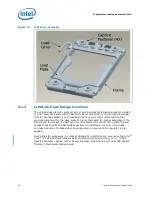
Страница 24: ...Independent Loading Mechanism ILM 24 Thermal Mechanical Design Guide Figure 3 3 ILM Assembly ...
Страница 26: ...Independent Loading Mechanism ILM 26 Thermal Mechanical Design Guide ...
Страница 48: ...Component Suppliers 48 Thermal Mechanical Design Guide ...
Страница 50: ...Mechanical Drawings 50 Thermal Mechanical Design Guide Figure B 1 Board Keepin Keepout Zones Sheet 1 of 4 ...
Страница 51: ...Thermal Mechanical Design Guide 51 Mechanical Drawings Figure B 2 Board Keepin Keepout Zones Sheet 2 of 4 ...
Страница 52: ...Mechanical Drawings 52 Thermal Mechanical Design Guide Figure B 3 Board Keepin Keepout Zones Sheet 3 of 4 ...
Страница 53: ...Thermal Mechanical Design Guide 53 Mechanical Drawings Figure B 4 Board Keepin Keepout Zones Sheet 4 of 4 ...
Страница 54: ...Mechanical Drawings 54 Thermal Mechanical Design Guide Figure B 5 1U Reference Heatsink Assembly Sheet 1 of 2 ...
Страница 55: ...Thermal Mechanical Design Guide 55 Mechanical Drawings Figure B 6 1U Reference Heatsink Assembly Sheet 2 of 2 ...
Страница 58: ...Mechanical Drawings 58 Thermal Mechanical Design Guide Figure B 9 Heatsink Shoulder Screw 1U 2U and Tower ...
Страница 59: ...Thermal Mechanical Design Guide 59 Mechanical Drawings Figure B 10 Heatsink Compression Spring 1U 2U and Tower ...
Страница 60: ...Mechanical Drawings 60 Thermal Mechanical Design Guide Figure B 11 Heatsink Retaining Ring 1U 2U and Tower ...
Страница 61: ...Thermal Mechanical Design Guide 61 Mechanical Drawings Figure B 12 Heatsink Load Cup 1U 2U and Tower ...
Страница 82: ...Mechanical Drawings 82 Thermal Mechanical Design Guide ...
Страница 88: ...Socket Mechanical Drawings 88 Thermal Mechanical Design Guide ...
Страница 95: ...Thermal Mechanical Design Guide 95 Embedded Thermal Solutions Figure E 5 UP ATCA Heat Sink Drawing ...
Страница 102: ...Processor Installation Tool 102 Thermal Mechanical Design Guide Figure F 1 Processor Installation Tool ...


