Embedded Thermal Solutions
96
Thermal/Mechanical Design Guide
E.3
Mechanical Drawings and Supplier Information
See
Appendix B
for retention and keep out drawings.
The part number below represent Intel reference designs for a DP ATCA heatsink.
Customer implementation of these components may be unique and require validation
by the customer. Customers can obtain these components directly from the supplier
below.
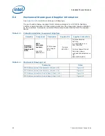
Table E-3.
Embedded Heatsink Component Suppliers
Assembly
Component
Description
Supplier PN
Supplier Contact Info
Assembly,
Heat Sink,
Nehalem-EP,
ATCA
ATCA
Reference
heatsink
Intel P/N
E65918-001
ATCA Copper
Fin, Copper
Base
Fujikura
HSA-7901
Fujikura America
Ash Ooe
[email protected]
408-748-6991
Fujikura Taiwan Branch
Yao-Hsien Huang
[email protected]
.tw
886(2)8788-4959
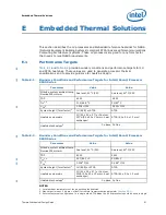
Table E-4.
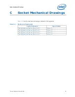
Mechanical Drawings List
Parameter
Value
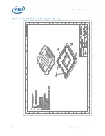
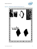
ATCA Reference Heat Sink Assembly (Sheet 1 of 2)
Figure E-6
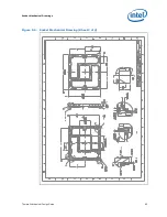
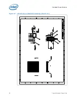
ATCA Reference Heat Sink Assembly (Sheet 2 of 2)
Figure E-7
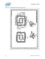
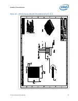
ATCA Reference Heatsink Fin and Base (Sheet 1 of 2)
Figure E-8
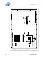
ATCA Reference Heatsink Fin and Base (Sheet 2 of 2)
Figure E-9
Содержание X5550 - Quad Core Xeon
Страница 8: ...8 Thermal Mechanical Design Guide ...
Страница 12: ...Introduction 12 Thermal Mechanical Design Guide ...
Страница 24: ...Independent Loading Mechanism ILM 24 Thermal Mechanical Design Guide Figure 3 3 ILM Assembly ...
Страница 26: ...Independent Loading Mechanism ILM 26 Thermal Mechanical Design Guide ...
Страница 48: ...Component Suppliers 48 Thermal Mechanical Design Guide ...
Страница 50: ...Mechanical Drawings 50 Thermal Mechanical Design Guide Figure B 1 Board Keepin Keepout Zones Sheet 1 of 4 ...
Страница 51: ...Thermal Mechanical Design Guide 51 Mechanical Drawings Figure B 2 Board Keepin Keepout Zones Sheet 2 of 4 ...
Страница 52: ...Mechanical Drawings 52 Thermal Mechanical Design Guide Figure B 3 Board Keepin Keepout Zones Sheet 3 of 4 ...
Страница 53: ...Thermal Mechanical Design Guide 53 Mechanical Drawings Figure B 4 Board Keepin Keepout Zones Sheet 4 of 4 ...
Страница 54: ...Mechanical Drawings 54 Thermal Mechanical Design Guide Figure B 5 1U Reference Heatsink Assembly Sheet 1 of 2 ...
Страница 55: ...Thermal Mechanical Design Guide 55 Mechanical Drawings Figure B 6 1U Reference Heatsink Assembly Sheet 2 of 2 ...
Страница 58: ...Mechanical Drawings 58 Thermal Mechanical Design Guide Figure B 9 Heatsink Shoulder Screw 1U 2U and Tower ...
Страница 59: ...Thermal Mechanical Design Guide 59 Mechanical Drawings Figure B 10 Heatsink Compression Spring 1U 2U and Tower ...
Страница 60: ...Mechanical Drawings 60 Thermal Mechanical Design Guide Figure B 11 Heatsink Retaining Ring 1U 2U and Tower ...
Страница 61: ...Thermal Mechanical Design Guide 61 Mechanical Drawings Figure B 12 Heatsink Load Cup 1U 2U and Tower ...
Страница 82: ...Mechanical Drawings 82 Thermal Mechanical Design Guide ...
Страница 88: ...Socket Mechanical Drawings 88 Thermal Mechanical Design Guide ...
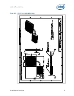
Страница 95: ...Thermal Mechanical Design Guide 95 Embedded Thermal Solutions Figure E 5 UP ATCA Heat Sink Drawing ...
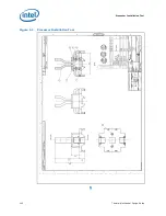
Страница 102: ...Processor Installation Tool 102 Thermal Mechanical Design Guide Figure F 1 Processor Installation Tool ...


