Embedded Thermal Solutions
92
Thermal/Mechanical Design Guide
socket only and the 38 W processor can be used in dual socket.
4. Local Ambient Temperature written 50/65
o
C means 50
o
C under Nominal conditions but 65
o
C is allowed for
Short-Term NEBS excursions.
5. Passive heatsinks with TIM.
6. See
Section 5.1
for standard 1U solutions that do not need to meet NEBS.
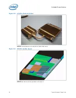
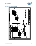
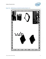
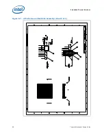
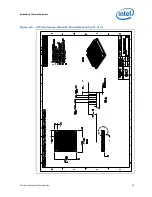
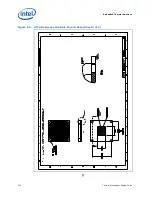
Detailed drawings for the ATCA reference heatsink can be found in
Section E.3
.
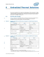
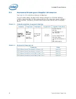
Table E-1
and
Table E-2
above specify
CA
targets.
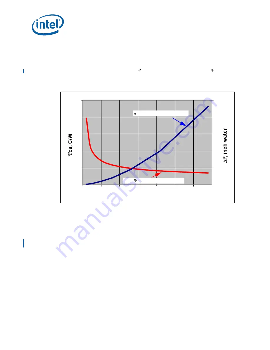
Figure E-1
below shows
CA
and
pressure drop for the ATCA heatsink versus the airflow provided. Best-fit equations are
provided to prevent errors associated with reading the graph.
Other LGA1366 compatible thermal solutions may work with the same retention.
E.2
Thermal Design Guidelines
E.2.1
NEBS Thermal Profile
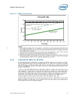
Processors that offer a NEBS compliant thermal profile are specified in the appropriate
Datasheet.
NEBS thermal profiles help relieve thermal constraints for Short-Term NEBS conditions.
To help reliability, processors must meet the nominal thermal profile under standard
operating conditions and can only rise up to the Short-Term spec for NEBS excursions
(see
Figure E-2
). The definition of Short-Term time is clearly defined for NEBS Level 3
conditions but the key is that it cannot be longer than 360 hours per year.
Figure E-1. ATCA Heatsink Performance Curves
0
0.4
0.8
1.2
1.6
2
0
0.5
1
1.5
2
2.5
0
5
10
15
20
25
30
35
CFM Through Fins
P = 1.3e-1.1e-02CFM
Mean
ca
= 0.337 + 1.625 CFM
-0.939
Содержание X5550 - Quad Core Xeon
Страница 8: ...8 Thermal Mechanical Design Guide ...
Страница 12: ...Introduction 12 Thermal Mechanical Design Guide ...
Страница 24: ...Independent Loading Mechanism ILM 24 Thermal Mechanical Design Guide Figure 3 3 ILM Assembly ...
Страница 26: ...Independent Loading Mechanism ILM 26 Thermal Mechanical Design Guide ...
Страница 48: ...Component Suppliers 48 Thermal Mechanical Design Guide ...
Страница 50: ...Mechanical Drawings 50 Thermal Mechanical Design Guide Figure B 1 Board Keepin Keepout Zones Sheet 1 of 4 ...
Страница 51: ...Thermal Mechanical Design Guide 51 Mechanical Drawings Figure B 2 Board Keepin Keepout Zones Sheet 2 of 4 ...
Страница 52: ...Mechanical Drawings 52 Thermal Mechanical Design Guide Figure B 3 Board Keepin Keepout Zones Sheet 3 of 4 ...
Страница 53: ...Thermal Mechanical Design Guide 53 Mechanical Drawings Figure B 4 Board Keepin Keepout Zones Sheet 4 of 4 ...
Страница 54: ...Mechanical Drawings 54 Thermal Mechanical Design Guide Figure B 5 1U Reference Heatsink Assembly Sheet 1 of 2 ...
Страница 55: ...Thermal Mechanical Design Guide 55 Mechanical Drawings Figure B 6 1U Reference Heatsink Assembly Sheet 2 of 2 ...
Страница 58: ...Mechanical Drawings 58 Thermal Mechanical Design Guide Figure B 9 Heatsink Shoulder Screw 1U 2U and Tower ...
Страница 59: ...Thermal Mechanical Design Guide 59 Mechanical Drawings Figure B 10 Heatsink Compression Spring 1U 2U and Tower ...
Страница 60: ...Mechanical Drawings 60 Thermal Mechanical Design Guide Figure B 11 Heatsink Retaining Ring 1U 2U and Tower ...
Страница 61: ...Thermal Mechanical Design Guide 61 Mechanical Drawings Figure B 12 Heatsink Load Cup 1U 2U and Tower ...
Страница 82: ...Mechanical Drawings 82 Thermal Mechanical Design Guide ...
Страница 88: ...Socket Mechanical Drawings 88 Thermal Mechanical Design Guide ...
Страница 95: ...Thermal Mechanical Design Guide 95 Embedded Thermal Solutions Figure E 5 UP ATCA Heat Sink Drawing ...
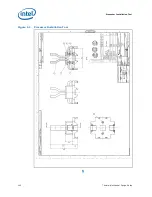
Страница 102: ...Processor Installation Tool 102 Thermal Mechanical Design Guide Figure F 1 Processor Installation Tool ...


