Quality and Reliability Requirements
42
Thermal/Mechanical Design Guide
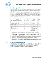
8a) Thermal
Performance for
Intel® Xeon®
Processor 5500 Series
Using 1U heatsink and 1U airflow from
Table 5-1
:
1) TTV @ 95W (Profile B), Note 1.
Using 2U heatsink and 2U airflow from
Table 5-1
:
2) TTV @ 95W (Profile A), Note 1.
3) TTV @ 80W.
4) TTV @ 60W.
Using Tower heatsink and Tower airflow
from
Table 5-1
:
5) TTV @ 130W, Note 1.
6) TTV @ 95W (Profile A).
7) TTV @ 80W.
8) TTV @ 60W.
As verified in wind tunnel:
1) mean
CA
+ 3s + offset not to exceed
Table 5-1
value for 95W in 1U.
2-4) mean
CA
+ 3s + offset not to exceed
Table 5-1
value for 2U.
5-8) mean
CA
+ 3s + offset not to exceed
Table 5-1
value for Tower.
5 heatsinks
X 8 tests by
supplier.
Note 1: 30
heatsinks X
3 tests by
Intel.
8b) Thermal
Performance for
Intel® Xeon®
Processor 5600 Series
Using 1U heatsink and 1U airflow from
Table 5-2
:
1) TTV @ 95W (Profile B), Note 1.
Using 2U heatsink and 2U airflow from
Table 5-2
:
2) TTV @ 130W, Note 1.
3) TTV @ 95W (Profile A).
4) TTV @ 80W.
5) TTV @ 60W.
As verified in wind tunnel:
1) mean
CA
+ 3s + offset not to exceed
Table 5-2
value for 95W in 1U.
2-5) mean
CA
+ 3s + offset not to exceed
Table 5-2
value for 2U.
Thermal
Test data
re-assessed
from Intel®
Xeon®
Processor
5500 Series
Qualification
9) Thermal Cycling
Required for heatpipe designs.
Temperature range at pipe in heatsink
assembly: -25C to +100C for 500 cycles.
Cycle time is 30 minutes per full cycle,
divided into half cycle in hot zone and half
in cold zone, with minimum 1min soak at
each temperature extreme for each cycle.
See
Figure 6-1
for example profile.
As verified in wind tunnel:
•
Mean
CA
+ 3s + offset not to exceed
value in
Table 5-1
and
Table 5-2
.
•
Pressure drop not to exceed value in
Table 5-1
and
Table 5-2
.
15
10) Heat Pipe Burst
Continuously raise oven temperature and
record the burst/leak temperatures of fully
assembled heatsinks
No failures at minimum of 300C @ 20
minutes
32 pipes
11) Heatsink Mass
Design Target < 500 g
All samples < 550 g
30
12) Heatsink Load
Design Targets:
0.062" board = 38.7 ± 7.2 lbf (Fmin =
31.5 lbf).
0.100" board = 51.4 ± 7.9 lbf (Fmax =
59.3 lbf).
No samples < 30 lbf on 0.062" board.
5 highest load samples (from 0.062" test)
< 60 lbf on 0.100" board
30
Table 6-1.
Heatsink Test Conditions and Qualification Criteria (Sheet 2 of 2)
Assessment
Test Condition
Qualification Criteria
Min
Sample
Size
Содержание X5550 - Quad Core Xeon
Страница 8: ...8 Thermal Mechanical Design Guide ...
Страница 12: ...Introduction 12 Thermal Mechanical Design Guide ...
Страница 24: ...Independent Loading Mechanism ILM 24 Thermal Mechanical Design Guide Figure 3 3 ILM Assembly ...
Страница 26: ...Independent Loading Mechanism ILM 26 Thermal Mechanical Design Guide ...
Страница 48: ...Component Suppliers 48 Thermal Mechanical Design Guide ...
Страница 50: ...Mechanical Drawings 50 Thermal Mechanical Design Guide Figure B 1 Board Keepin Keepout Zones Sheet 1 of 4 ...
Страница 51: ...Thermal Mechanical Design Guide 51 Mechanical Drawings Figure B 2 Board Keepin Keepout Zones Sheet 2 of 4 ...
Страница 52: ...Mechanical Drawings 52 Thermal Mechanical Design Guide Figure B 3 Board Keepin Keepout Zones Sheet 3 of 4 ...
Страница 53: ...Thermal Mechanical Design Guide 53 Mechanical Drawings Figure B 4 Board Keepin Keepout Zones Sheet 4 of 4 ...
Страница 54: ...Mechanical Drawings 54 Thermal Mechanical Design Guide Figure B 5 1U Reference Heatsink Assembly Sheet 1 of 2 ...
Страница 55: ...Thermal Mechanical Design Guide 55 Mechanical Drawings Figure B 6 1U Reference Heatsink Assembly Sheet 2 of 2 ...
Страница 58: ...Mechanical Drawings 58 Thermal Mechanical Design Guide Figure B 9 Heatsink Shoulder Screw 1U 2U and Tower ...
Страница 59: ...Thermal Mechanical Design Guide 59 Mechanical Drawings Figure B 10 Heatsink Compression Spring 1U 2U and Tower ...
Страница 60: ...Mechanical Drawings 60 Thermal Mechanical Design Guide Figure B 11 Heatsink Retaining Ring 1U 2U and Tower ...
Страница 61: ...Thermal Mechanical Design Guide 61 Mechanical Drawings Figure B 12 Heatsink Load Cup 1U 2U and Tower ...
Страница 82: ...Mechanical Drawings 82 Thermal Mechanical Design Guide ...
Страница 88: ...Socket Mechanical Drawings 88 Thermal Mechanical Design Guide ...
Страница 95: ...Thermal Mechanical Design Guide 95 Embedded Thermal Solutions Figure E 5 UP ATCA Heat Sink Drawing ...
Страница 102: ...Processor Installation Tool 102 Thermal Mechanical Design Guide Figure F 1 Processor Installation Tool ...


