Introduction
10
Thermal/Mechanical Design Guide
1.1
References
Material and concepts available in the following documents may be beneficial when
reading this document.
Notes:
1.
Document numbers indicated in Location column are subject to change. See the appropriate Electronic
Design Kit (EDK) for the most up-to-date Document number.
2.
Available at http://www.blauer-engel.de
3.
Available at http://ssiforum.org/
1.2
Definition of Terms
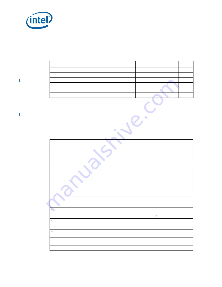
Table 1-1.
Reference Documents
Document
Location
Notes
European Blue Angel Recycling Standards
2
Intel® Xeon® Processor 5500 Series Datasheet, Volume 1
321321
1
Intel® Xeon® Processor 5600 Series Datasheet, Volume 1
323369
1
Intel® Xeon® Processor 5500 Series Mechanical Model
321326
1
Intel® Xeon® Processor 5500 Series Thermal Model
321327
1
Entry-level Electronics Bay Specification
3
Table 1-2.
Terms and Descriptions (Sheet 1 of 2)
Term
Description
Bypass
Bypass is the area between a passive heatsink and any object that can act to form a
duct. For this example, it can be expressed as a dimension away from the outside
dimension of the fins to the nearest surface.
DTS
Digital Thermal Sensor reports a relative die temperature as an offset from TCC
activation temperature.
FSC
Fan Speed Control
IHS
Integrated Heat Spreader: a component of the processor package used to enhance the
thermal performance of the package. Component thermal solutions interface with the
processor at the IHS surface.
ILM
Independent Loading Mechanism provides the force needed to seat the 1366-LGA land
package onto the socket contacts.
LGA1366 socket
The processor mates with the system board through this surface mount, 1366-contact
socket.
PECI
The Platform Environment Control Interface (PECI) is a one-wire interface that provides
a communication channel between Intel processor and chipset components to external
monitoring devices.
CA
Case-to-ambient thermal characterization parameter (psi). A measure of thermal
solution performance using total package power. Defined as (T
CASE
– T
LA
) / Total
Package Power. Heat source should always be specified for measurements.
CS
Case-to-sink thermal characterization parameter. A measure of thermal interface
material performance using total package power. Defined as (T
CASE
– T
S
) / Total
Package Power.
SA
Sink-to-ambient thermal characterization parameter. A measure of heatsink thermal
performance using total package power. Defined as (T
S
– T
LA
) / Total Package Power.
T
CASE
The case temperature of the processor measured at the geometric center of the topside
of the IHS.
T
CASE
_
MAX
The maximum case temperature as specified in a component specification.
Содержание X5550 - Quad Core Xeon
Страница 8: ...8 Thermal Mechanical Design Guide ...
Страница 12: ...Introduction 12 Thermal Mechanical Design Guide ...
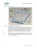
Страница 24: ...Independent Loading Mechanism ILM 24 Thermal Mechanical Design Guide Figure 3 3 ILM Assembly ...
Страница 26: ...Independent Loading Mechanism ILM 26 Thermal Mechanical Design Guide ...
Страница 48: ...Component Suppliers 48 Thermal Mechanical Design Guide ...
Страница 50: ...Mechanical Drawings 50 Thermal Mechanical Design Guide Figure B 1 Board Keepin Keepout Zones Sheet 1 of 4 ...
Страница 51: ...Thermal Mechanical Design Guide 51 Mechanical Drawings Figure B 2 Board Keepin Keepout Zones Sheet 2 of 4 ...
Страница 52: ...Mechanical Drawings 52 Thermal Mechanical Design Guide Figure B 3 Board Keepin Keepout Zones Sheet 3 of 4 ...
Страница 53: ...Thermal Mechanical Design Guide 53 Mechanical Drawings Figure B 4 Board Keepin Keepout Zones Sheet 4 of 4 ...
Страница 54: ...Mechanical Drawings 54 Thermal Mechanical Design Guide Figure B 5 1U Reference Heatsink Assembly Sheet 1 of 2 ...
Страница 55: ...Thermal Mechanical Design Guide 55 Mechanical Drawings Figure B 6 1U Reference Heatsink Assembly Sheet 2 of 2 ...
Страница 58: ...Mechanical Drawings 58 Thermal Mechanical Design Guide Figure B 9 Heatsink Shoulder Screw 1U 2U and Tower ...
Страница 59: ...Thermal Mechanical Design Guide 59 Mechanical Drawings Figure B 10 Heatsink Compression Spring 1U 2U and Tower ...
Страница 60: ...Mechanical Drawings 60 Thermal Mechanical Design Guide Figure B 11 Heatsink Retaining Ring 1U 2U and Tower ...
Страница 61: ...Thermal Mechanical Design Guide 61 Mechanical Drawings Figure B 12 Heatsink Load Cup 1U 2U and Tower ...
Страница 82: ...Mechanical Drawings 82 Thermal Mechanical Design Guide ...
Страница 88: ...Socket Mechanical Drawings 88 Thermal Mechanical Design Guide ...
Страница 95: ...Thermal Mechanical Design Guide 95 Embedded Thermal Solutions Figure E 5 UP ATCA Heat Sink Drawing ...
Страница 102: ...Processor Installation Tool 102 Thermal Mechanical Design Guide Figure F 1 Processor Installation Tool ...


