Thermal/Mechanical Design Guide
13
LGA1366 Socket
2
LGA1366 Socket
This chapter describes a surface mount, LGA (Land Grid Array) socket intended for
processors in the Intel® Xeon® 5500 Platform. The socket provides I/O, power and
ground contacts. The socket contains 1366 contacts arrayed about a cavity in the
center of the socket with lead-free solder balls for surface mounting on the
motherboard.
The socket has 1366 contacts with 1.016 mm X 1.016 mm pitch (X by Y) in a
43x41 grid array with 21x17 grid depopulation in the center of the array and selective
depopulation elsewhere.
The socket must be compatible with the package (processor) and the Independent
Loading Mechanism (ILM). The design includes a back plate which is integral to having
a uniform load on the socket solder joints. Socket loading specifications are listed in
Chapter 4
.
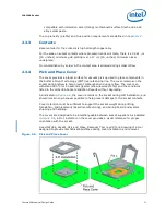
Figure 2-1.
LGA1366 Socket with Pick and Place Cover Removed
socket
cavity
package
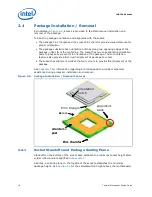
socket
cavity
package
Содержание X5550 - Quad Core Xeon
Страница 8: ...8 Thermal Mechanical Design Guide ...
Страница 12: ...Introduction 12 Thermal Mechanical Design Guide ...
Страница 24: ...Independent Loading Mechanism ILM 24 Thermal Mechanical Design Guide Figure 3 3 ILM Assembly ...
Страница 26: ...Independent Loading Mechanism ILM 26 Thermal Mechanical Design Guide ...
Страница 48: ...Component Suppliers 48 Thermal Mechanical Design Guide ...
Страница 50: ...Mechanical Drawings 50 Thermal Mechanical Design Guide Figure B 1 Board Keepin Keepout Zones Sheet 1 of 4 ...
Страница 51: ...Thermal Mechanical Design Guide 51 Mechanical Drawings Figure B 2 Board Keepin Keepout Zones Sheet 2 of 4 ...
Страница 52: ...Mechanical Drawings 52 Thermal Mechanical Design Guide Figure B 3 Board Keepin Keepout Zones Sheet 3 of 4 ...
Страница 53: ...Thermal Mechanical Design Guide 53 Mechanical Drawings Figure B 4 Board Keepin Keepout Zones Sheet 4 of 4 ...
Страница 54: ...Mechanical Drawings 54 Thermal Mechanical Design Guide Figure B 5 1U Reference Heatsink Assembly Sheet 1 of 2 ...
Страница 55: ...Thermal Mechanical Design Guide 55 Mechanical Drawings Figure B 6 1U Reference Heatsink Assembly Sheet 2 of 2 ...
Страница 58: ...Mechanical Drawings 58 Thermal Mechanical Design Guide Figure B 9 Heatsink Shoulder Screw 1U 2U and Tower ...
Страница 59: ...Thermal Mechanical Design Guide 59 Mechanical Drawings Figure B 10 Heatsink Compression Spring 1U 2U and Tower ...
Страница 60: ...Mechanical Drawings 60 Thermal Mechanical Design Guide Figure B 11 Heatsink Retaining Ring 1U 2U and Tower ...
Страница 61: ...Thermal Mechanical Design Guide 61 Mechanical Drawings Figure B 12 Heatsink Load Cup 1U 2U and Tower ...
Страница 82: ...Mechanical Drawings 82 Thermal Mechanical Design Guide ...
Страница 88: ...Socket Mechanical Drawings 88 Thermal Mechanical Design Guide ...
Страница 95: ...Thermal Mechanical Design Guide 95 Embedded Thermal Solutions Figure E 5 UP ATCA Heat Sink Drawing ...
Страница 102: ...Processor Installation Tool 102 Thermal Mechanical Design Guide Figure F 1 Processor Installation Tool ...


