Thermal/Mechanical Design Guide
31
Thermal Solutions
5
Thermal Solutions
This section describes a 1U reference heatsink, design targets for 2U and Tower
heatsinks, performance expectations for a 25.5 mm tall heatsink, and thermal design
guidelines for processors in the Intel® Xeon® 5500 Platform.
5.1
Performance Targets
Values for boundary conditions and performance targets are used to generate
processor thermal specifications and to provide guidance for heatsink design.
Notes:
1. Local ambient temperature of the air entering the heatsink.
2. Max target (mean + 3 sigma + offset) for thermal characterization parameter (
Section 5.5.1
).
Table 5-1.
Boundary Conditions and Performance Targets for Intel® Xeon® Processor
5500 Series
Parameter
Value
Altitude, system
ambient temp
Sea level, 35
o
C
TDP
60W
80W
95W, Profile B
95W, Profile A
130W, WS
9
T
LA
1
49
o
C
49
o
C
49
o
C
55
o
C
40
o
C
CA
2
0.335
o
C/W
0.336
o
C/W
0.337
o
C/W
0.201
o
C/W
0.201
o
C/W
Airflow
3
9.7 CFM @
0.20” dP
9.7 CFM @
0.20” dP
9.7 CFM @
0.20” dP
30 CFM @
0.173” dP
30 CFM @
0.173” dP
System height
(form factor)
4
1U (EEB)
1U (EEB)
1U (EEB)
5
2U (EEB)
Pedestal (EEB)
Heatsink
volumetric
90 x 90 x 27mm (1U)
6
90 x 90 x 64mm
(2U)
6,7
90 x 90 x 99mm
(Tower)
6
Heatsink
technology
8
Cu base, Al fins
Cu/Al base, Al fins with heatpipes
Table 5-2.
Boundary Conditions and Performance Targets for Intel Xeon processor 5600
series
Parameter
Value
Altitude, system
ambient temp
Sea level, 35
o
C
TDP
40W
60W
80W
95W, Profile B
95W, Profile A
130W
T
LA
1
49
o
C
55
o
C
53
o
C
CA
2
(6 core)
n/a
0.340ºC/W
0.340ºC/W
0.340ºC/W
0.200ºC/W
0.196ºC/W
CA
2
(4 core)
0.353ºC/W
n/a
0.357ºC/W
0.357
o
C/W
0.217
o
C/W
0.211
o
C/W
Airflow
3
9.7 CFM @ 0.20” dP
30 CFM @
0.173” dP
35 CFM @
0.214” dP
System height
(form factor)
4
1U (EEB)
2U (EEB)
Heatsink
volumetric
90 x 90 x 27mm (1U)
6
90 x 90 x 64mm (2U)
6,7
Heatsink
technology
8
Cu base, Al fins
Cu/Al base, Al fins with
heatpipes
Содержание X5550 - Quad Core Xeon
Страница 8: ...8 Thermal Mechanical Design Guide ...
Страница 12: ...Introduction 12 Thermal Mechanical Design Guide ...
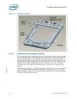
Страница 24: ...Independent Loading Mechanism ILM 24 Thermal Mechanical Design Guide Figure 3 3 ILM Assembly ...
Страница 26: ...Independent Loading Mechanism ILM 26 Thermal Mechanical Design Guide ...
Страница 48: ...Component Suppliers 48 Thermal Mechanical Design Guide ...
Страница 50: ...Mechanical Drawings 50 Thermal Mechanical Design Guide Figure B 1 Board Keepin Keepout Zones Sheet 1 of 4 ...
Страница 51: ...Thermal Mechanical Design Guide 51 Mechanical Drawings Figure B 2 Board Keepin Keepout Zones Sheet 2 of 4 ...
Страница 52: ...Mechanical Drawings 52 Thermal Mechanical Design Guide Figure B 3 Board Keepin Keepout Zones Sheet 3 of 4 ...
Страница 53: ...Thermal Mechanical Design Guide 53 Mechanical Drawings Figure B 4 Board Keepin Keepout Zones Sheet 4 of 4 ...
Страница 54: ...Mechanical Drawings 54 Thermal Mechanical Design Guide Figure B 5 1U Reference Heatsink Assembly Sheet 1 of 2 ...
Страница 55: ...Thermal Mechanical Design Guide 55 Mechanical Drawings Figure B 6 1U Reference Heatsink Assembly Sheet 2 of 2 ...
Страница 58: ...Mechanical Drawings 58 Thermal Mechanical Design Guide Figure B 9 Heatsink Shoulder Screw 1U 2U and Tower ...
Страница 59: ...Thermal Mechanical Design Guide 59 Mechanical Drawings Figure B 10 Heatsink Compression Spring 1U 2U and Tower ...
Страница 60: ...Mechanical Drawings 60 Thermal Mechanical Design Guide Figure B 11 Heatsink Retaining Ring 1U 2U and Tower ...
Страница 61: ...Thermal Mechanical Design Guide 61 Mechanical Drawings Figure B 12 Heatsink Load Cup 1U 2U and Tower ...
Страница 82: ...Mechanical Drawings 82 Thermal Mechanical Design Guide ...
Страница 88: ...Socket Mechanical Drawings 88 Thermal Mechanical Design Guide ...
Страница 95: ...Thermal Mechanical Design Guide 95 Embedded Thermal Solutions Figure E 5 UP ATCA Heat Sink Drawing ...
Страница 102: ...Processor Installation Tool 102 Thermal Mechanical Design Guide Figure F 1 Processor Installation Tool ...

