LGA1366 Socket
20
Thermal/Mechanical Design Guide
2.9
LGA1366 Socket NCTF Solder Joints
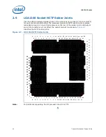
Intel has defined selected solder joints of the socket as non-critical to function (NCTF)
for post environmental testing. The processor signals at NCTF locations are typically
redundant ground or non-critical reserved, so the loss of the solder joint continuity at
end of life conditions will not affect the overall product functionality.
Figure 2-7
identifies the NCTF solder joints.
.
Note:
For platforms supporting the DP processor land C3 is CTF.
§
Figure 2-7.
LGA1366 NCTF Solder Joints
A
C
E
G
J
L
N
R
U
W
AA AC AE AG AJ
AL AN AR AU AW BA
B
D
F
H
K
M
P
T
V
Y
AB AD AF AH AK AM AP AT AV AY
1
3
7
5
9
11
15
13
17
19
23
21
25
27
31
29
1
3
7
5
9
11
15
13
17
19
23
21
25
27
31
29
2
8
4
6
10
16
12
14
18
24
20
22
26
32
28
30
2
8
4
6
10
16
12
14
18
24
20
22
26
32
28
30
16
12
15
13
14
17
18
24
20
19
23
21
22
25
26
32
28
27
31
29
30
33
34
40
36
35
39
37
38
41
42
43
B
D
F
H
K
M
P
T
V
Y
AB AD AF AH AK AM AP AT AV AY
A
C
E
G
J
L
N
R
U
W
AA AC AE AG AJ
AL AN AR AU AW BA
Содержание X5550 - Quad Core Xeon
Страница 8: ...8 Thermal Mechanical Design Guide ...
Страница 12: ...Introduction 12 Thermal Mechanical Design Guide ...
Страница 24: ...Independent Loading Mechanism ILM 24 Thermal Mechanical Design Guide Figure 3 3 ILM Assembly ...
Страница 26: ...Independent Loading Mechanism ILM 26 Thermal Mechanical Design Guide ...
Страница 48: ...Component Suppliers 48 Thermal Mechanical Design Guide ...
Страница 50: ...Mechanical Drawings 50 Thermal Mechanical Design Guide Figure B 1 Board Keepin Keepout Zones Sheet 1 of 4 ...
Страница 51: ...Thermal Mechanical Design Guide 51 Mechanical Drawings Figure B 2 Board Keepin Keepout Zones Sheet 2 of 4 ...
Страница 52: ...Mechanical Drawings 52 Thermal Mechanical Design Guide Figure B 3 Board Keepin Keepout Zones Sheet 3 of 4 ...
Страница 53: ...Thermal Mechanical Design Guide 53 Mechanical Drawings Figure B 4 Board Keepin Keepout Zones Sheet 4 of 4 ...
Страница 54: ...Mechanical Drawings 54 Thermal Mechanical Design Guide Figure B 5 1U Reference Heatsink Assembly Sheet 1 of 2 ...
Страница 55: ...Thermal Mechanical Design Guide 55 Mechanical Drawings Figure B 6 1U Reference Heatsink Assembly Sheet 2 of 2 ...
Страница 58: ...Mechanical Drawings 58 Thermal Mechanical Design Guide Figure B 9 Heatsink Shoulder Screw 1U 2U and Tower ...
Страница 59: ...Thermal Mechanical Design Guide 59 Mechanical Drawings Figure B 10 Heatsink Compression Spring 1U 2U and Tower ...
Страница 60: ...Mechanical Drawings 60 Thermal Mechanical Design Guide Figure B 11 Heatsink Retaining Ring 1U 2U and Tower ...
Страница 61: ...Thermal Mechanical Design Guide 61 Mechanical Drawings Figure B 12 Heatsink Load Cup 1U 2U and Tower ...
Страница 82: ...Mechanical Drawings 82 Thermal Mechanical Design Guide ...
Страница 88: ...Socket Mechanical Drawings 88 Thermal Mechanical Design Guide ...
Страница 95: ...Thermal Mechanical Design Guide 95 Embedded Thermal Solutions Figure E 5 UP ATCA Heat Sink Drawing ...
Страница 102: ...Processor Installation Tool 102 Thermal Mechanical Design Guide Figure F 1 Processor Installation Tool ...


