


4-20
BUS PROTOCOL
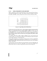
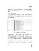
In T6, agent 0 issues another transaction, and in T8, the internal state is updated appropriately.
In the series of clocks indicated in the diagram by T10, five more transactions become outstand-
ing (this status is indicated by the {rcnt}). In T13, the 8th transaction is issued as indicated on
the bus by ADS# assertion in T13. In T15, the {rcnt} is incremented to 8, the highest possible
value for {rcnt}. No additional transactions can be issued until a response is given for
transaction 0.
4.2.3.
Request Phase Protocol Rules
4.2.3.1.
REQUEST GENERATION
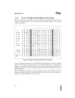
The Request Phase is always one clock of active ADS# followed by one clock of inactive ADS#.
There is always an idle clock between request phases for bus turnaround. Address, command,
and parity information is transferred on the first two clocks on pins A[35:3]#, REQ[4:0]#, and
AP[1:0]# and RP#. Refer to Chapter 3, Bus Overview for a description of which signals are driv-
en on these pins. Although LOCK# is part of the Arbitration Phase, it is driven during the first
clock of the Request Phase. AP[1:0]# and RP# are valid during a valid Request Phase.
On observation of a new request, the transaction counts including {rcnt} and {scnt} are updated
with the new transaction.
4.2.3.2.
REQUEST PHASE QUALIFIERS
The Request Phase for a new transaction may be initiated when:
•
The agent contains one or more pending requests.
•
The agent owns the bus as described in the Arbitration Phase section.
•
The internal request count state is less than the maximum number of entries in the IOQ.
•
The bus is not stalled. In other words, the Request Stall state (as described in Section 4.1.,
“Arbitration Phase”) is free or throttled.
•
The preceding transaction’s Request Phase is complete. In other words, ADS# is observed
inactive on the previous clock.
4.3.
ERROR PHASE
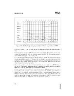
Receiving agents use the Error Phase to indicate parity errors in Request Phase. Parity is checked
during valid Request Phase (One clock active ADS# followed by one clock inactive ADS#) on
AP[1:0]# and RP# signals.
If the request parity is enabled in the power-on configuration as described in Chapter 9, Config-
uration, then the agent checks parity in the two clocks. If transaction cancellation due to AERR#
is enabled (AERR# observation) in the power-on-configuration and AERR# is observed active
Содержание Pentium Pro Family
Страница 17: ...1 Component Introduction ...
Страница 26: ...2 Pentium Pro Processor Architecture Overview ...
Страница 27: ......
Страница 36: ...3 Bus Overview ...
Страница 62: ...4 Bus Protocol ...
Страница 105: ...5 Bus Transactions and Operations ...
Страница 126: ...6 Range Registers ...
Страница 131: ...7 Cache Protocol ...
Страница 135: ...8 Data Integrity ...
Страница 148: ...9 Configuration ...
Страница 161: ...10 Pentium Pro Processor Test Access Port TAP ...
Страница 172: ...11 Electrical Specifications ...
Страница 201: ...12 GTL Interface Specification ...
Страница 229: ...13 3 3V Tolerant Signal Quality Specifications ...
Страница 233: ...14 Thermal Specifications ...
Страница 239: ...15 Mechanical Specifications ...
Страница 241: ...15 2 MECHANICAL SPECIFICATIONS s Figure 15 1 Package Dimensions Bottom View ...
Страница 252: ...16 Tools ...
Страница 260: ...16 8 TOOLS Figure 16 4 Generic MP System Layout for Debug Port Connection ...
Страница 264: ...17 OverDrive Processor Socket Specification ...
Страница 290: ...A Signals Reference ...
Страница 320: ...Index ...
Страница 328: ......