


17-11
OVERDRIVE® PROCESSOR SOCKET SPECIFICATION
17.3.
FUNCTIONAL OPERATION OF OVERDRIVE
®
PROCESSOR
SIGNALS
17.3.1.
Fan/Heatsink Power (VCC5)
This 5V supply provides power to the fan of the fan/heatsink assembly. See Table 17-4 for Vcc5
specifications.
17.3.2.
Upgrade Present Signal (UP#)
The Upgrade Present signal is used to prevent operation of voltage regulators providing a poten-
tially harmful voltage to the OverDrive processor, and to prevent contention between on-board
regulation and the OverDrive VRM. UP# is an open collector output, held high using a pull-up
resistor on the motherboard tied to +5 Volts.
There are several system voltage regulation design options to support both the Pentium Pro pro-
cessor and its OverDrive processor. The use of the UP# signal for each case is described below:
— Case 1: Header 8 only
If the system is designed with voltage regulation from the Header 8 only, then the UP#
signal must be connected between the CPU socket (Socket 8) and the VRM connector
(Header 8). The Pentium Pro processor VRM should internally connect the UP# input
directly to the VRM OUTEN input. If the Pentium Pro processor is replaced with an
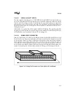
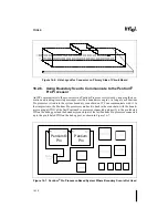
Figure 17-6. OverDrive
®
Voltage Regulator Module Envelope
P6T005
0.550 MIN
0.550 REF
0.090 REF
OverDrive VRM PCB
HEADER 8
DIMENSIONS IN INCHES
3.00 REF
AAAA
AAAA
AAAA
AAAA
AAAA
AAAA
AAAA
AAAA
AAAA
2.4
Total height
from
motherboard
to an
immovable
object
0.80
Max Component
Height on front
of VRM PCB
0.14
Max Component
Height on back
of VRM PCB
1.8
Total space
for VRM /
Header 8
from
motherboard
3.10 Max VRM PCB Width
Minimum distance to VRM
components from motherboard
R
NOTE: The connector comprises a header mounted on the motherboard and a receptacle on the edge of the VRM PCB.
Содержание Pentium Pro Family
Страница 17: ...1 Component Introduction ...
Страница 26: ...2 Pentium Pro Processor Architecture Overview ...
Страница 27: ......
Страница 36: ...3 Bus Overview ...
Страница 62: ...4 Bus Protocol ...
Страница 105: ...5 Bus Transactions and Operations ...
Страница 126: ...6 Range Registers ...
Страница 131: ...7 Cache Protocol ...
Страница 135: ...8 Data Integrity ...
Страница 148: ...9 Configuration ...
Страница 161: ...10 Pentium Pro Processor Test Access Port TAP ...
Страница 172: ...11 Electrical Specifications ...
Страница 201: ...12 GTL Interface Specification ...
Страница 229: ...13 3 3V Tolerant Signal Quality Specifications ...
Страница 233: ...14 Thermal Specifications ...
Страница 239: ...15 Mechanical Specifications ...
Страница 241: ...15 2 MECHANICAL SPECIFICATIONS s Figure 15 1 Package Dimensions Bottom View ...
Страница 252: ...16 Tools ...
Страница 260: ...16 8 TOOLS Figure 16 4 Generic MP System Layout for Debug Port Connection ...
Страница 264: ...17 OverDrive Processor Socket Specification ...
Страница 290: ...A Signals Reference ...
Страница 320: ...Index ...
Страница 328: ......