


16-3
TOOLS
16.2.4.
Signal Notes
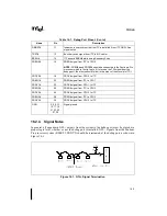
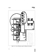
In general, all open drain GTL+ outputs from the system to the debug port must be placed at a
proper logic level, whether or not the debug port is installed. GTL+ signals from the Pentium
Pro processor system (RESET#, PRDY#) should be terminated at the debug port, as shown in
Figure 16-1.
DBINST#
11
Indicates to user system that the ITP is installed (from ITP GND). See
signal note 4
TRST#
12
Boundary scan signal from ITP to MP cluster
BSEN#
14
ITP asserts BSEN# while using Boundary Scan
PREQ0#
16
PREQ# signal from ITP to CPU 0
NOTE: PREQ0# and PRDY0# should be connected to the Pentium
®
Pro
processor which is first (of up to 4) to receive the TDI signal from the
debug port; the others should follow in the order of their receipt of TDI
PRDY0#
18
PRDY# signal from CPU 0 to ITP
PREQ1#
20
PREQ# signal from ITP to CPU 1
PRDY1#
22
PRDY# signal from CPU 1 to ITP
PREQ2#
24
PREQ# signal from ITP to CPU 2
PRDY2#
26
PRDY# signal from CPU 2 to ITP
PREQ3#
28
PREQ# signal from ITP to CPU 3
PRDY3#
30
PRDY# signal from CPU 3 to ITP
GND
2, 4, 6, 13,
15, 17, 19,
21, 23, 25,
27, 29
Signal ground
Figure 16-1. GTL+ Signal Termination
Table 16-1. Debug Port Pinout (Contd.)
Name
Pin
Description
Содержание Pentium Pro Family
Страница 17: ...1 Component Introduction ...
Страница 26: ...2 Pentium Pro Processor Architecture Overview ...
Страница 27: ......
Страница 36: ...3 Bus Overview ...
Страница 62: ...4 Bus Protocol ...
Страница 105: ...5 Bus Transactions and Operations ...
Страница 126: ...6 Range Registers ...
Страница 131: ...7 Cache Protocol ...
Страница 135: ...8 Data Integrity ...
Страница 148: ...9 Configuration ...
Страница 161: ...10 Pentium Pro Processor Test Access Port TAP ...
Страница 172: ...11 Electrical Specifications ...
Страница 201: ...12 GTL Interface Specification ...
Страница 229: ...13 3 3V Tolerant Signal Quality Specifications ...
Страница 233: ...14 Thermal Specifications ...
Страница 239: ...15 Mechanical Specifications ...
Страница 241: ...15 2 MECHANICAL SPECIFICATIONS s Figure 15 1 Package Dimensions Bottom View ...
Страница 252: ...16 Tools ...
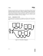
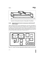
Страница 260: ...16 8 TOOLS Figure 16 4 Generic MP System Layout for Debug Port Connection ...
Страница 264: ...17 OverDrive Processor Socket Specification ...
Страница 290: ...A Signals Reference ...
Страница 320: ...Index ...
Страница 328: ......