


9-7
CONFIGURATION
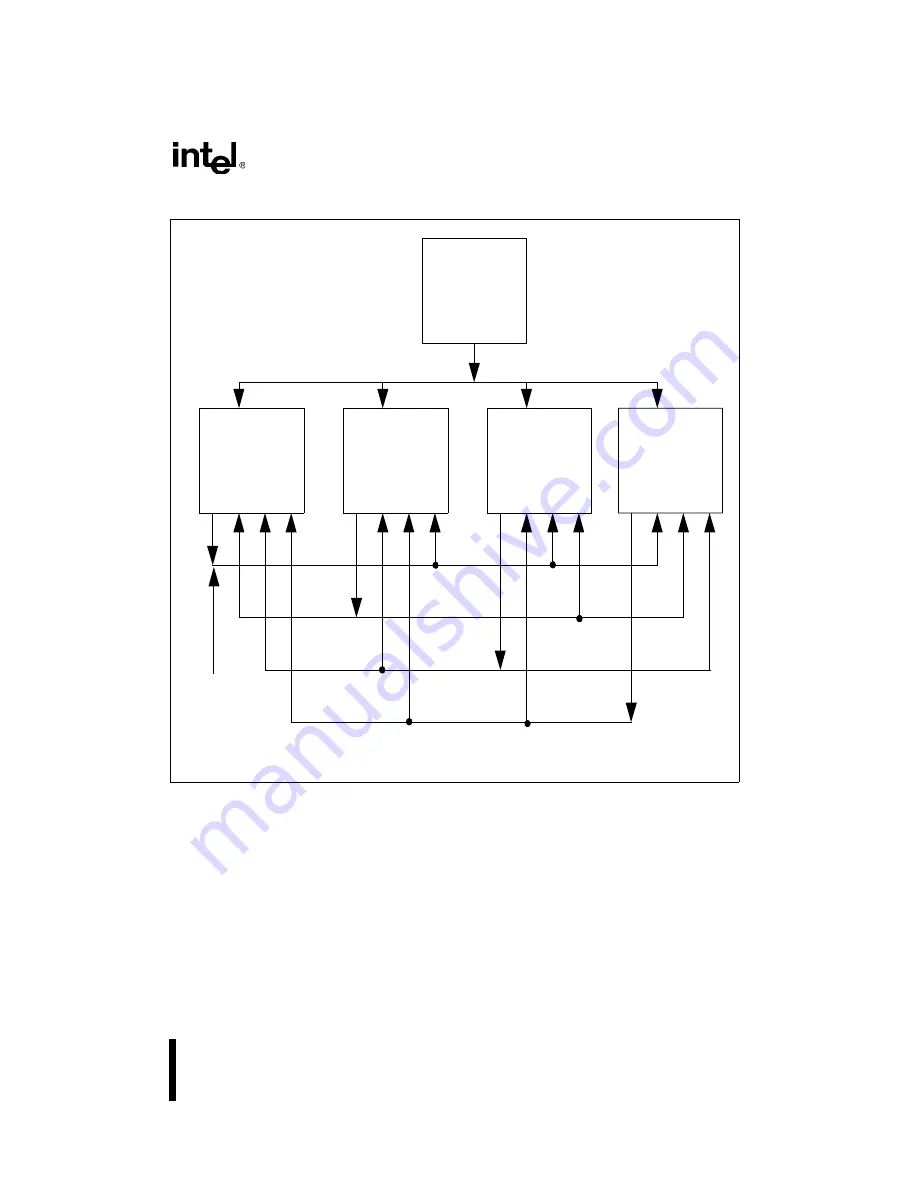
At the RESET# signal’s active-to-inactive transition, system interface logic is responsible for as-
sertion of the BREQ0# bus signal. BREQ[3:1]# bus signals remain deasserted. All Pentium Pro
processors sample their BR[3:1]# pins on the RESET signal’s active-to-inactive transition and
determine their agent ID from the sampled value.
If FRC is not enabled, then each physical processor is a logical processor. Each processor is des-
ignated a non-FRC master and each processor has a distinct agent ID.
Figure 9-2. BR[3:0]# Physical Interconnection
Agent 0
Agent 1
Agent 2
Agent 3
BR1
#
BR2
#
BR3
#
BREQ0#
BREQ1#
BREQ2#
BREQ3#
Priority
BPRI#
Agent
BR0
#
BR0
#
BR0
#
BR0
#
BR1
#
BR1
#
BR1
#
BR2
#
BR2
#
BR2
#
BR3
#
BR3
#
BR3
#
System
Interface Logic
During Reset
Содержание Pentium Pro Family
Страница 17: ...1 Component Introduction ...
Страница 26: ...2 Pentium Pro Processor Architecture Overview ...
Страница 27: ......
Страница 36: ...3 Bus Overview ...
Страница 62: ...4 Bus Protocol ...
Страница 105: ...5 Bus Transactions and Operations ...
Страница 126: ...6 Range Registers ...
Страница 131: ...7 Cache Protocol ...
Страница 135: ...8 Data Integrity ...
Страница 148: ...9 Configuration ...
Страница 161: ...10 Pentium Pro Processor Test Access Port TAP ...
Страница 172: ...11 Electrical Specifications ...
Страница 201: ...12 GTL Interface Specification ...
Страница 229: ...13 3 3V Tolerant Signal Quality Specifications ...
Страница 233: ...14 Thermal Specifications ...
Страница 239: ...15 Mechanical Specifications ...
Страница 241: ...15 2 MECHANICAL SPECIFICATIONS s Figure 15 1 Package Dimensions Bottom View ...
Страница 252: ...16 Tools ...
Страница 260: ...16 8 TOOLS Figure 16 4 Generic MP System Layout for Debug Port Connection ...
Страница 264: ...17 OverDrive Processor Socket Specification ...
Страница 290: ...A Signals Reference ...
Страница 320: ...Index ...
Страница 328: ......