background image


61


Operations


Using the Listening Modes


—Continued


The RDC-7.1 provides various listening modes.


Note:


The available modes depend on the input signal you 
selected. 


Operating on the RDC

7.1


Operating with the Remote Controller


Tip:


A table listed later in this manual shows which listening 
mode can be used with which input signal format. See 
page 143.


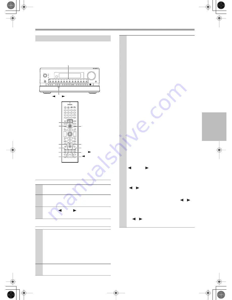
Selecting the Listening Mode


1


Press the input source button.


2


Start playback on the device you selected 
for input.


3


Use the [

] DSP [

] buttons to select a 

listening mode.


1


Roll the scroll wheel to select a device for play-
back.


Perform this operation when neither the [Mode] 
button nor the [Input] button lights. If any button 
lights, press it to turn it off.
Rolling the scroll wheel lights both buttons, and 
switches the input source and the mode at the 
same time.


2


Start playback on the device you selected 
for input.

ABC

DEF

PQRS

TUV

WXYZ

GHI

JKL

MNO

Caps

Delete

Language

Loca t ion

Album

Ar tist

Genre

Playlist

Repeat

Video

Music

Photo

@.-'/

--/---

Direct Tuning

#

Custom

Display

Dimmer

T V 

Input

Sleep

Random

Main A      Main B 

Muting

Angle

Subtitle

Audio

Memory

Search

A-B

Repeat

On

Standby

T V

T V CH

T V VOL

Exit

Gu

ide

Rec

Last Memory

Prev

CH

Enter

Set

up

Retu

rn

Test Tone

CH SEL

Pure A

Surround

Direct

Stereo

Re-EQ

THX

All CH ST

Level +

Level -

L Night

Audio SEL

DSP

DSP

+10

0

Clear

1

2

3

4

5

6

7

8

9

Input

To

p M

enu

Men

u

VOL

CH
Disc

I

+

-

+

-

Zone 3

Zone 2

Input

Mode

Macro

Se

rve

r

Aud

io

A

D

J

On

Standby/On

Standby

Pure Audio

On

Master  Volume

Power

DVD

Video 

1

Video 

2

Video 

3

Video 

4

Video 

5

Video 

6

Video 

7

Tape 

1

Tape 

2

Tuner

Phono

Net Audio

C D

Open/Close

Zone

 2 (

)

GRN

Rec/ Zone

 3 (

)

RED

O f f

Phones

Clear

Rec/ Zone 

3

Zone 

2

Off

DSP

Display

Tuning

Tuning Mode

Preset

Memory

Setup

Exit

Enter

Dimmer

AV Controller

  RDC-7.1

Mode

Surround

THX

Stereo

All CH ST

Direct

Pure A

DSP

Input

DSP

DSP

Input source buttons

Scroll wheel

RC-554M
RC-555M


3


Press the scroll wheel, and then press the 
listening mode button you want to select.


Pure A button: 


To switch the listening mode to 

“Pure Audio.” When you select “PURE AUDIO,” 
the video signal is interrupted (resulting in a 
blacked-out screen), and the [Pure Audio] indica-
tor lights up.


Direct button: 


To switch the listening mode to 

“Direct.”


Stereo button:


 To switch the listening mode to 

“Stereo.” 


Surround button:


 To switch the listening mode 

to the surround mode.
• When 5 channel signals are input, every time 

you press the button, the listening mode 
changes “DolbyEX” 


“PLIIx Movie 

(Default)” 


“PLIIx Music” 


 “NEO:6” 


“Off” 


 “DolbyEX,” and so on. 

• When 2 channel signals are input, every time 

you press the button, the listening mode 
changes “PLIIx Movie (Default)” 


 “PLIIx 

Music” 


 “PLIIx Game” 


 “NEO:6 Cinema” 


 “NEO:6 Music” 


 “PLIIx Movie 

(Default),” and so on.


THX button: 


To switch the listening mode to 

“THX.”
• When Dolby Digital multichannel (*/2) signals 

are input, you can switch to any of the 
following decode modes. Every time you press 
the button, the listening mode changes “THX 
Cinema” 


 “SurroundEX” 


→ 


“Ultra2 Cinema 

(Default)” 


 “MusicMode”


 “Games Mode” 


 “THX Cinema,” and so on (See page 115).


DSP/DSP


buttons: 


Every time you press 

the buttons, you can switch to any of the listening 
modes according to the input signals. 


ALL ST button:


 To switch the listening mode to 

“All Ch Stereo.”


[

]/[

] cursor buttons:


• When AAC’s multiplex sound signals are 

input, the main-sound and sub-sound are 
switched. Every time you press the [

]/[

buttons, the mode changes “Main”


 →


“Sub” 


“Main + Sub” 


“Main,” and so on.

• When using the headphones, you can use the 

[

]/[

] buttons to switch on/off the Dolby 

Headphone listening mode.

Содержание Integra Research RDC-7.1

Страница 1: ...AV Controller RDC 7 1 Instruction Manual...

Страница 2: ...aratus does not operate normally by following the operating instructions Adjust only those controls that are covered by the operating instructions as an improper adjustment of other controls may resul...

Страница 3: ...ng as that indicated on the plug Check for the ASTA mark or the BSI mark on the body of the fuse IF THE FITTED MOULDED PLUG IS UNSUITABLE FOR THE SOCKET OUTLET IN YOUR HOME THEN THE FUSE SHOULD BE REM...

Страница 4: ...rnal Device with 12V Trigger Terminal USA and Canadian models 47 Connecting Components not Reached by the Remote Controller Signals IR IN OUT Other than USA and Canadian models 48 If Remote Controller...

Страница 5: ...15 All Ch Stereo Setup Full Mono Setup Sub menu 116 Dolby Virtual Speaker Setup Sub menu 117 Dolby Headphone Setup Sub menu 118 Audio Adjust 119 Tone Control Sub menu 119 Preference 120 Volume Setup S...

Страница 6: ...d B Mode for 7 1 Channels Bi Wiring Connectable for FL FR with SBR SBL Dual 32 Bit DSP Chips for high grade main and multizone decoding 5 12V DC Trigger Outputs and 3 IR Inputs Outputs for multizone o...

Страница 7: ...protected by U S patents and other intellectual property rights Use of this copyright protection technology must be authorized by Macrovision Corporation and is intended for home and other limited co...

Страница 8: ...ght Front Right SP B Zone 2 Right SP B Zone 2 Right Front Right Front Right SP B Zone 2 Right SP B Zone 2 Right Surround Right Surround Right Center Center Center Center Surround Left Surround Left Su...

Страница 9: ...t that uses infrared rays the remote controller may not work reliably Don t put anything such as a book on the remote controller because the buttons may be pressed inadvertently thereby draining the b...

Страница 10: ...7 1 The specifications for your model may differ due to regional requirements Front Panel On Standby On Standby Pure Audio On Master Volume Power DVD Video 1 Video 2 Video 3 Video 4 Video 5 Video 6 V...

Страница 11: ...en a signal is received from the remote controller 4 Remote control sensor 9 5 Front display 6 Master Volume dial 52 Use to control the volume in the main zone The volume for the remote zone Zone 2 an...

Страница 12: ...rding component for recording purposes or enter the Zone 3 mode After pressing the Rec Zone 3 button press one of the input source selector buttons within 3 seconds to select the component When one is...

Страница 13: ...fic program and then back to RT again G Tuning button 62 Use these buttons to change the tuner frequency The tuner frequency is displayed in the front display and it can be changed in 50 kHz increment...

Страница 14: ...d four output jacks are available for each of VIDEO and S VIDEO connection 9 COMPONENT VIDEO IN OUT Only available as option for the USA model These connectors are for connecting to the component vide...

Страница 15: ...wer amplifiers If the jacks on your power amplifier are XLR balanced type jacks connect them here H AC INLET This connector is for connecting the supplied power cord A Listening mode or input format i...

Страница 16: ...es 7 Dimmer button This button is used to adjust the display brightness 8 Up Down Left Right Enter buttons These buttons are used to select items on the onscreen setup menus OSD The ENTER button is al...

Страница 17: ...ton is used when you want to set the volume and input source for Zone 2 N Input button This button is used to select the input source Press this button first and then roll the scroll wheel until the n...

Страница 18: ...the volume level between speakers See pages 92 to 94 Basic Speaker Placements for Home Theater and the Function of Respective Speakers Center speaker Complements the sound effects from front left and...

Страница 19: ...behind the listener Place the surround speakers symmetrically from the listener position and so that the distance from the listener is equal between left and right surround speakers When enjoying mai...

Страница 20: ...in one cycle 0 to 360 degrees of a sine wave If the phase does not match between multiple waveforms due to the distance between multiple speakers the speaker orientation or the miswiring of positive a...

Страница 21: ...output through the surround speakers 5 ch 5 1 ch This placement is suitable for playing 5 1 ch sources includinganalogmultichannel Dolby Digital DTS and AAC format sources When the source is 2 ch or m...

Страница 22: ...ic Set all the zone parameters for speaker system A to Main A Set the front speaker parameters for speaker system B to Main A If you want to use the front speakers of speaker system B for specific sou...

Страница 23: ...ker system A set the surround back speaker parameters to Bi Amp for Front and all the other speaker parameters to Main A For details on speaker connections see page 27 For speaker system B set the spe...

Страница 24: ...and subwoofer of speaker system B for specific sources select the source and set the parameters for these speakers to B or A B in the listening mode setup menu When you set the parameter to B the aud...

Страница 25: ...ACK RIGHT SURROUND RIGHT 12V TRIGGER IN OUT SURROUND LEFT CENTER FRONT LEFT SURROUND BACK LEFT FRONT RIGHT INPUT SELECT INPUT SELECT INPUT SELECT INPUT SELECT INPUT SELECT INPUT SELECT OUTPUT OUTPUT O...

Страница 26: ...mplifier Using XLR Type Cables 1 GND 2 non inverting 3 inverting XLR type Balanced cable Push L R L R FRONT CENTER SURR SURR BACK SUB WOOFER SURR BACK R SURR R FRONT R CENTER FRONT L SURR BACK L SURR...

Страница 27: ...d the woofer terminal of the right speaker to the SURROUND BACK RIGHT terminal on the power amplifier 3 Connect the tweeter terminal of the left speaker to the FRONT LEFT terminal on the power amplifi...

Страница 28: ...R R L GND OUT L R L R R L F G L IN 1 IN 2 HDMI the HDMI logo is a trademark or registered trademarks of HDMI Licensing LLC OUT HDMI S VIDEO VIDEO IN IN IN 1 IN 2 3 2 1 Y PB PR COMPONENT VIDEO IN 3 I H...

Страница 29: ...good reception cannot be achieved using the supplied AM loop antenna an outdoor AM antenna can be used in addition to the loop antenna as shown Outdoor AM antennas work best when installed outside ho...

Страница 30: ...cal cables have their own covers Before making a connection remove the cov ers When plugging in a cable be sure to match the connector shape with the terminal shape Each optical terminal on the RDC 7...

Страница 31: ...2 or VIDEO 3 terminal Cable names Cable forms Terminals shapes Description Component video connection cable RCA type In this connection the video signal is decom posed into three color difference sig...

Страница 32: ...he remote zone Zone 2 or Zone 3 the TV or monitor should be connected to the VIDEO 1 VIDEO 2 or VIDEO 3 terminal For more information on the HDMI interface see page 43 Connecting Monitors such as TV o...

Страница 33: ...terminal to connect a TV or projector For more information on the HDMI interface see page 43 For more information on the i LINK AUDIO interface see page 40 Connecting a DVD Player L L SINGLE ASSIGNAB...

Страница 34: ...ith the VIDEO 1 as input Connecting a DVD Recorder or Digital VCR VIDEO 1 ASSIGNABLE ASSIGNABLE REMOTE CONTROL Net Tune is a trademark of Onkyo Corporation ETHERNET Net Tune 2 2 1 1 6 6 5 5 4 4 3 3 2...

Страница 35: ...RNET Net Tune 2 2 1 1 6 6 5 5 4 4 3 3 2 2 1 1 C D DIGITAL IN DIGITAL IN OPTICAL COAXIAL OUT SBR SBL SR SL SUB C FR FL E MULTI CH IN 1 DIGITAL IN BALANCED AES EBU DIGITAL IN BALANCED AES EBU AUDIO IN 1...

Страница 36: ...Y PB PR COMPONENT OUT BNC R L ANALOG S VIDEO IN AUDIO IN R L ANALOG AUDIO OUT S VIDEO OUT VIDEO OUT AUDIO OUT DIGITAL OPTICAL When connecting to other audio terminals within the same terminal section...

Страница 37: ...a trademark of Onkyo Corporation ETHERNET Net Tune 2 2 1 1 6 6 5 5 4 4 3 3 2 2 1 1 C D DIGITAL IN DIGITAL IN OPTICAL COAXIAL OUT SBR SBL SR SL SUB C FR FL E MULTI CH IN 1 DIGITAL IN BALANCED AES EBU D...

Страница 38: ...table is equipped with a ground wire connect the wire to the GND terminal on the RDC 7 1 However some turntables may produce noise when the ground wire is connected to the RDC 7 1 In such a case you d...

Страница 39: ...e to the AUDIO IN terminals on the RDC 7 1 using analog audio cables RCA phono Connecting a Recording Device such as MD Recorder DAT Deck CD Recorder or Cassette Deck ASSIGNABLE ASSIGNABLE REMOTE CONT...

Страница 40: ...nsfer between the i LINK connected digital devices in order to protect the copyright of the content against illegal duplication To enjoy replaying DVD Audio etc the DTCP must also be supported by othe...

Страница 41: ...terminals The RDC 7 1 has a maximum data transfer rate of 400 Mbps However this may decrease depending on the specifications or the maxi mum data transfer rate of devices connected to the RDC 7 1 It i...

Страница 42: ...the i LINK connected device starts playing the input source will automatically be changed to the one assigned to the device even if another input source has been selected See page 121 for detailed ope...

Страница 43: ...digital display interface standard set by DDWG 3 in 1999 2 HDCP High bandwidth Digital Contents Protection The video data encryption technology for DVI developed by Intel This technology is designed...

Страница 44: ...N 12V TRIGGER OUT IR UPP D E 200mA MAX 100mA MAX 100mA MAX 100mA MAX 100mA MAX ZONE 2 ZONE 3 L R L R CENTER SURR FRONT SURR BACK SUB WOOFER PRE OUT B AC INLET MODEL NO RDC 7 1 ASSIGNABLE SINGLE RS232...

Страница 45: ...cted components using the system do not use the remote zone Zone 2 Zone 3 For remote control operation the audio connection cables must also be connected If a component has two terminals you can use e...

Страница 46: ...and ZONE 2 connect all the red wires to the 12V ter minal together 4 Connect the black wire to the GND terminal and then close the shutter If you use more than one multi room kit in different rooms co...

Страница 47: ...R SURR BACK SUB WOOFER SURR BACK R SURR R FRONT R CENTER FRONT L SURR BACK L SURR L SUBWOOFER PRE OUT A ASSIGNABLE SINGLE SINGLE ASSIGNABLE ASSIGNABLE Net Tune is a trademark of Onkyo Corporation ETHE...

Страница 48: ...be sensed Example for the remote zone Zone 2 Zone 3 The IR IN input allows you to control the RDC 7 1 from the remote zone Zone 2 Zone 3 with the remote controller even though the remote zone may be...

Страница 49: ...with the output signal from the RDC 7 1 s 12V TRIGGER OUT terminal Making a Connection Connect the 12V TRIGGER OUT terminal on the RDC 7 1 to the 12V TRIGGER IN terminal on other components Every 12V...

Страница 50: ...EL Level On Standby Setup Enter Return Cursor RC 554M RC 555M Scroll wheel 1 Press the scroll wheel 2 When the remote controller is in AMP mode the following functions are available On Standby Press t...

Страница 51: ...ndby TV TV CH TV VOL 10 0 Clear 1 2 3 4 5 6 7 8 9 Input Top Menu Menu I Zone3 Zone2 Input Mode Macro Server Audio A Mode Scroll wheel 1 Press the Mode button The Mode button lights 2 Roll the scroll w...

Страница 52: ...g on the Power 1 Plug the power cord into an AC wall outlet Press the Power switch to set the RDC 7 1 to standby state The Standby indicator will light up 2 Press the Standby On button to turn on the...

Страница 53: ...m where you want to play your device Main A Switches to operations in main room A Main B Switches to operations in main room B When Main A or Main B is selected the indicator on the front display of t...

Страница 54: ...MNO Direct Tuning Custom Display Dimmer TV Input Sleep Muting On Standby TV TV CH TV VOL Exit Guide Prev CH Enter Setup Return 10 0 Clear 1 2 3 4 5 6 7 8 9 Input Top Menu Menu VOL CH Disc I Zone3 Zon...

Страница 55: ...own The specified sleep time appears on the display for about five seconds then the previous display reappears Note Ifyouareusingtheremotezone Zone2or 3 it will turn off at the same time as the main z...

Страница 56: ...if the source material has been recorded at a higher or lower level than usual For example if you see the message Dialog Norm 4 in the front panel display to keep the overall output level constant th...

Страница 57: ...trong treble level to the home theater level This correction should be made when the treble sounds from the front speakers are too strong Hint This can also be set on the menu with OSD The listening m...

Страница 58: ...Game This is the best mode for enjoying games providing the best sense of signal movement Dolby Digital This is a surround mode that will make you feel as if you are sitting in a seat inside a theate...

Страница 59: ...s It enables 7 1 channel playback of 5 1 channel recorded sources THX Games Mode This is the THX Ultra 2 mode designed for playing game sources THX Surround EX THX Surround EX Dolby Digital Surround E...

Страница 60: ...DTS format Listening modes when the Dolby Headphone is set to Off Direct When the listening mode was Direct before putting on headphones this mode is applied Effects are the same as the Direct mode i...

Страница 61: ...one 3 Zone 2 Off DSP Display Tuning Tuning Mode Preset Memory Setup Exit Enter Dimmer AV Controller RDC 7 1 Mode Surround THX Stereo All CH ST Direct Pure A DSP Input DSP DSP Input source buttons Scro...

Страница 62: ...o the FM station in stereo press the Tuning Mode button Specifying Radio Stations by Frequency To select a radio station by entering its frequency press the remote controller s Direct Tuning button an...

Страница 63: ...eo 5 Video 6 Video 7 Tape 1 Tape 2 Tuner Phono Net Audio C D Open Close Zone 2 GRN Rec Zone 3 RED O f f Phones Clear Rec Zone 3 Zone 2 Off DSP Display Tuning Tuning Mode Preset Memory Setup Exit Enter...

Страница 64: ...s may appear on the display if the RDC 7 1 receives characters that cannot be displayed correctly This is not a malfunction When an RDS station broadcasting PS information is selected the name of the...

Страница 65: ...eo 7 Tape 1 Tape 2 Tuner Phono Net Audio C D Open Close Zone 2 GRN Rec Zone 3 RED O f f Phones Clear Rec Zone 3 Zone 2 Off DSP Display Tuning Tuning Mode Preset Memory Setup Exit Enter RT PTY TP AV Co...

Страница 66: ...D DIGITAL IN DIGITAL IN OPTICAL COAXIAL OUT SBR SBL SR SL SUB C FR FL E MULTI CH IN 1 DIGITAL IN BALANCED AES EBU DIGITAL IN BALANCED AES EBU AUDIO IN 1 3 2 1 PH 2 3 9 8 7 6 5 4 4 5 L R R L GND OUT L...

Страница 67: ...vel in the range from 81 5 dB to 18 0 dB when Relative is set for Volume Setup Caps Delete Language Location Album Artist Genre Playlist Repeat Video Music Photo Display Dimmer TV Input Sleep Random M...

Страница 68: ...Zone 2 or Zone 3 to the RDC 7 1 Connect to any of the following terminals AUDIO OUT 1 5 Default Analog 4 AUDIO OUT 4 Zone 2 Out Analog 5 AUDIO OUT 5 Zone 3 Out DIGITAL OUT OPTICAL 1 2 DIGITAL OUT COAX...

Страница 69: ...OUT 1 5 DIGITAL OUT OPTICAL 1 2 DIGITAL OUT COAXIAL 1 2 2 Connect the speakers for Zone 2 or Zone 3 to the power amplifier 3 Connect the video component for Zone 2 or Zone 3 to any of the composite VI...

Страница 70: ...one CH SEL Pure A Surround Direct Stereo Re EQ THX AllCHST Level Level L Night AudioSEL DSP DSP 10 0 Clear 1 2 3 4 5 6 7 8 9 Input Top Menu Menu VOL CH Disc I Zone3 Zone2 Input Mode Macro Server Audio...

Страница 71: ...l Signals from the DIGITAL IN OPTICAL or COAX IAL jacks are output to the DIGITAL OUT OPTI CAL or COAXIAL jacks PCM signals are converted into analog signals and also output to the AUDIO OUT jacks Vid...

Страница 72: ...also dis abled on the same component as that for playing On Standby On Standby Pure Audio On Master Volume Power DVD Video 1 Video 2 Video 3 Video 4 Video 5 Video 6 Video 7 Tape 1 Tape 2 Tuner Phono N...

Страница 73: ...from Another Source 1 Turn on the power supply to the RDC 7 1 in MAIN A or MAIN B mode 2 Check connections and settings to the recording component Refer to steps 2 and 3 in RecordingAudio Video While...

Страница 74: ...T For best results a 100Base T switched Ethernet network is recommended Although it s theoretically possible to use a wireless network due to unpredictable perfor mance it may not provide satisfactor...

Страница 75: ...parate rooms simultaneously The following diagram shows a Net Tune network with two RDC 7 1s Networking Your RDC 7 1 L R L R FRONT CENTER SURR SURR BACK SUB WOOFER SURR BACK R SURR R FRONT R CENTER FR...

Страница 76: ...make playlists of your favorite tracks Computer Requirements The computer requirements necessary for running the Net Tune Central server software are as follows Operating system Windows XP or 2000 Ma...

Страница 77: ...c database you want to access See page 99 When you use a broadband router with the DHCP function enabled the network settings will be configured automati cally In this case you do not have to make any...

Страница 78: ...op line and NET T in the bottom line Using the Remote Controller ABC DEF PQRS TUV WXYZ GHI JKL MNO Caps Delete Language Location Album Artist Genre Playlist Repeat Video Music Photo Direct Tuning Cust...

Страница 79: ...lbum button This button is used to search the Net Tune server s music library by album 0 Playlist button This button is used to search the Net Tune server s library by playlist A Caps button This butt...

Страница 80: ...eo 3 Video 4 Video 5 Video 6 Video 7 Tape 1 Tape 2 Tuner Phono Net Audio C D Open Close Zone 2 GRN Rec Zone 3 RED O f f Phones Clear Rec Zone 3 Zone 2 Off DSP Display Tuning Tuning Mode Preset Memory...

Страница 81: ...g the OSD screen all the information is displayed on one screen without scrolling 1 Receive your desired station 2 Press the button The RDC 7 1 enters into preset mode the currently selected preset nu...

Страница 82: ...s between two alter native settings Server and Internet Radio Until the RDC 7 1 connects to the net work finds the server and completes the connection Network Starting and Connecting appears After com...

Страница 83: ...mode to display it in the display In the artist and album modes the tracks are displayed in alphabetical order You can also use the procedure below 1 Press the Display button 2 You can press the butt...

Страница 84: ...3 Zone2 Input Mode Macro Server Audio A D J Input Setup Enter Scroll wheel Input Enter Enter 4 Use the buttons to select the Music Server sub menu then press the Enter button The setup screen for the...

Страница 85: ...85 Operations Connecting Net Audio Other than USA Canada and Australian models Continued Music Server Memo Internet Radio Memo...

Страница 86: ...LINK Setup 7 Network Setup 8 Lock Version 1 Speaker Output Setup 1 Speaker Configuration 2 Speaker Crossover 3 Speaker Distance 4 Notch Filter 5 Level Calibration 6 THX Audio Setup 7 Audio Output Assi...

Страница 87: ...Setup 8 Lock Version 4 Audio Adjust 1 Tone Control 5 Preference 1 Volume Setup 2 Headphone Level Setup 3 OSD Setup 4 OSD Position 7 Network Setup 1 IP Address 2 Proxy 3 MAC Address 4 Client Save Setti...

Страница 88: ...0 Hardware Setup 1 TV Format Setup 1 Speaker Setup 1 Speaker Crossover 2 Speaker Distance 3 Level Calibration 4 THX Audio Setup 2 Input Setup Input XXXXXXXXX 1 Listening Mode Preset 2 Delay 3 Audio A...

Страница 89: ...up 3 Stereo Setup 4 Dolby Digital Setup 5 DTS Setup 6 AAC Setup 7 Dolby Virtual Speaker Setup Zone 2 Setup 0 Hardware Setup 1 Input Setup 2 Listening Mode Setup 3 Audio Adjust 4 Preference The Zone 2...

Страница 90: ...On Standby TV TV CH TV VOL Exit Guide Rec Last Memory Prev CH Enter Setup Return TestTone CH SEL Pure A Surround Direct Stereo Re EQ THX AllCHST Level Level L Night AudioSEL DSP DSP 10 0 Clear 1 2 3...

Страница 91: ...d See Changing the Remote Controller s Control ID on page 142 to change the remote control ID for the remote controller TV Format for all models other than USA and Canadian models The settings in the...

Страница 92: ...when using a subwoofer in main room A Not Used Select this when not using a subwoofer in main room A Speaker B Front L R Main A Select this when using in main room A Main B Select this when using in...

Страница 93: ...ain B Perform the setup procedure below following the operating instructions described on page 90 1 Select the unit of distance from Unit You can select either feet or meters The default varies depend...

Страница 94: ...nt speaker press the buttons to select a speaker and press the buttons to set the volume level When you have set all connected speakers the setup is complete You can adjust in the range from 12 dB to...

Страница 95: ...ample 1 When input REC of an audio recording device e g a cassette deck with TAPE 1 as an input source is connected to AUDIO OUT 1 set Analog 1 to Tape 1 Rec Out Example 2 When sound input of a pictur...

Страница 96: ...The default settings are as follows Composite Video 1 3 S Video 1 3 This is a setting for the composite video output jacks VIDEO OUT 1 3 and S video output jacks S VIDEO OUT 1 3 For Composite Video 1...

Страница 97: ...UDIO you can specify settings for the server See page 99 Settings defaults are as follows Note Defaults may differ depending on your region or option board in use USA USA and Canadian models OSD Indic...

Страница 98: ...he device connected to AUDIO IN PH 1 9 Select the device connected to the jack of AUDIO IN 1 9 No Select this when no device is connected Multichannel This item appears when the multichannel terminal...

Страница 99: ...er than PCM is input there is no sound Note When playing any DTS type CD or LD always select Auto and DTS Selecting PCM will cause noises i LINK This item appears when the i LINK AUDIO terminal board...

Страница 100: ...rom the listening modes listed below Main A B Pure Audio Direct Stereo Mono Dolby Digital Default THX Mono Movie Enhance Orchestra Unplugged Studio Mix TV Logic All Ch Stereo Full Mono Dolby VS and La...

Страница 101: ...specify the listening mode for playing audio output signals at 192 kHz and 176 4 kHz such as DVD Audio This option can be set for Main B and Zone 2 as well as for Main A You can select from the liste...

Страница 102: ...ing the delay in time will expand the sound field while reducing the distance narrowing the delay will make the sound field sharper When the 12V TRIGGER OUT jack on the RDC 7 1 is connected to the 12V...

Страница 103: ...nfiguration When the Speaker B Front L R is set to an option other than Main A in the Speaker Configuration sub menu the available options will be Center A Center B Center A B and Front L R A When the...

Страница 104: ...ting can be made when the Speaker A Subwoofer is set to an option other than Not Used in the Speaker Configuration sub menu However when the Speaker B Subwoofer is set to an option other than Main A i...

Страница 105: ...igured to Speaker A and Speaker B d Surr Bk Speaker This option configures the surround back speakers to use when playing the source in the Direct or Pure Audio listening mode Select the speakers you...

Страница 106: ...r A B Outputs the source from the center speaker configured to Speaker B A B Outputs the source from the center speakers configured to Speaker A and Speaker B e Surr L R Sp This option configures the...

Страница 107: ...de when the Speaker B Front L R is set to Main A in the Speaker Configuration sub menu A Default Outputs the source from the front speakers configured to Speaker A B Outputs the source from the front...

Страница 108: ...onfiguration sub menu you cannot select PLIIx Movie PLIIx Music Plays a 5 1ch source as a 6 1 or higher channel source using the Dolby Pro Logic IIx Music mode NEO 6 Plays a 5 1ch source as a 6 1 or h...

Страница 109: ...his option can also be set for Zone 2 b Late Night This option allows you to set how the Late Night function works See page 57 The setting you select here will be applied to all of the Dolby Digital i...

Страница 110: ...r B Surr Back in the Speaker Configuration sub menu differ the available options will be A and B A Default Outputs the source from the surround back speakers configured to Speaker A B Outputs the sour...

Страница 111: ...uts the source from the surround speakers configured to Speaker A and Speaker B g Surr Bk Speaker This option configures the surround back speakers to use when playing the source in the DTS listening...

Страница 112: ...er speaker configured to Speaker B A B Outputs the source from the center speakers configured to Speaker A and Speaker B f Surr L R Sp This option configures the surround speakers to use when playing...

Страница 113: ...t like a mono source or is too narrow move the sound space backward to obtain a better balance d PLIIx Music Center Width This option allows you to adjust the sound image width which the center speake...

Страница 114: ...her than Not Used in the Speaker Configuration sub menu However when the Speaker B Subwoofer is set to an option other than Main A in the Speaker Configuration sub menu the available options will be A...

Страница 115: ...eaker A B Outputs the source from the surround speakers configured to Speaker B A B Outputs the source from the surround speakers configured to Speaker A and Speaker B g Surr Bk Speaker This option co...

Страница 116: ...to use This setting can be made when the Speaker B Surr L R is set to Main A in the Speaker Configuration sub menu A Default Outputs the source from the surround speakers configured to Speaker A B Ou...

Страница 117: ...puts the source from the surround speakers configured to Speaker B A B Outputs the source from the surround speakers configured to Speaker A and Speaker B e Surr Bk Speaker This option configures the...

Страница 118: ...ured to Speaker A and Speaker B e Subwoofer This option configures the subwoofer to use when playing the source Select the terminal to which the subwoofer you want to use is connected This setting can...

Страница 119: ...urr L R Bass Option for adjusting bass notes from surround L R speakers Specify at 1 dB intervals in a range from 12 dB to 12 dB The default is 0 Surr L R Mid Option for adjusting mid notes from surro...

Страница 120: ...nent Video Specify whether or not to display the On Screen Display OSD on the screen when both of the source device and TV projector are connected to the component video terminals This option can be s...

Страница 121: ...ld display the OSD screen using the cursor buttons if multiple IntegraRESEARCH i LINK AUDIO ready devices are connected to the RDC 7 1 This item does not appear when Disable is selected in the OSD for...

Страница 122: ...directly to the RDC 7 1 enter the gateway address provided by your ISP e DNS Server 1 DNS Server 2 Specify if Disable is selected in a DHCP Settings When an xDSL modem or a terminal adapter is connect...

Страница 123: ...etting saving data will take a few seconds While saving data be sure not to turn off the power otherwise the data will be lost Specifications Ethernet port 10BASE T File type MP3 WMA WAV supports non...

Страница 124: ...V component and your RDC 7 1 even if they are con nected digitally DVD mode is used to control an IntegraRESEARCH Onkyo DVD player connected to the RDC 7 1 via To select DVD mode press the Mode button...

Страница 125: ...VD playback C Step Slow buttons These buttons are used for frame by frame play back and slow motion playback D Subtitle button This button is used to select subtitles E Audio button This button is use...

Страница 126: ...rrent track The Next button is used to select the next track 7 FR FF buttons The FR button is used to start fast reverse The FF button is used to start fast forward 8 Pause button This button is used...

Страница 127: ...t the current disc or track including the elapsed time remaining time total time and so on 5 Previous Next buttons The Previous button is used to select the pre vious track During playback it selects...

Страница 128: ...4 Rec button This button is used to start tape recording 5 LIGHT button This button is used to turn on or off the remote con troller s illuminated buttons 6 Input button This button is used to select...

Страница 129: ...doesn t have an socket or you re not using Point the remote controller at the DVD player to operate it Entering a Remote Control Code 1 Look up the appropriate remote control code for the component Se...

Страница 130: ...ri 4017 Hirschmann 4019 4035 Hitachi 4036 4037 Hughes Network Systems 4011 Huth 4013 4015 4024 Imperial 4014 Intertronic 4013 Intervision 4015 4023 4024 Johansson 4015 JVC 4009 4021 Kathrein 4025 Kolo...

Страница 131: ...Finlandia 2034 2036 Finlux 2034 2036 2037 Firstline 2033 2041 Fisher 2007 2030 2036 Fuji 2004 2010 2024 Funai 2012 Garrard 2012 GE 2001 2002 2008 2010 2011 2023 2025 2026 GEC 2034 GoldHand 2033 GoldS...

Страница 132: ...a 1040 Bruns 1040 BSR 1048 Bush 1035 1043 1048 1050 1053 1057 Cascade 1035 Celebrity 1002 Century 1040 Cimline 1035 1043 Citizen 1004 1006 1009 1017 1022 1025 Clatronic 1052 Colortyme 1004 1006 Condor...

Страница 133: ...Shack Realistic 1001 1004 1006 1007 1009 1010 1017 1021 1025 Radiola 1037 Radiomarelli 1040 1067 RCA 1001 1003 1004 1005 1006 1008 1027 1034 Realistic 1010 1017 1034 Rex 1045 1062 RFT 1040 Roadstar 1...

Страница 134: ...mbers VOL Adjust the RDC 7 1 volume Muting Mute the RDC 7 1 ABC DEF PQRS TUV WXYZ GHI JKL MNO Caps Delete Language Location Album Artist Genre Playlist Repeat Video Music Photo Direct Tuning Custom Di...

Страница 135: ...r buttons Enter numbers CH Disc Select cable channels TV Input Select TV or VCR input TV VOL Adjust the TV volume VOL Adjust the RDC 7 1 volume Muting Mute the RDC 7 1 ABC DEF PQRS TUV WXYZ GHI JKL MN...

Страница 136: ...aught a command simply repeat this proce dure Like most remote controllers the RDC 7 1 s remote controller uses infrared Commands from remote controllers that don t use infrared cannot be learned When...

Страница 137: ...ode 2 Roll the scroll wheel to select MACRO and then press the scroll wheel 3 Roll the scroll wheel to select EDIT and then press the scroll wheel 4 Roll the scroll wheel to select a macro and then pr...

Страница 138: ...scroll wheel to select MACRO and then press the scroll wheel 3 Roll the scroll wheel to select NAME and then press the scroll wheel 4 Roll the scroll wheel to select the number of the macro that you...

Страница 139: ...ll wheel to select ADD and then press the scroll wheel 4 Roll the scroll wheel to select the type of mode you want to add and then press the scroll wheel You can add up to 8 additional modes for examp...

Страница 140: ...select MODE and then press the scroll wheel 3 Roll the scroll wheel to select DEL and then press the scroll wheel 4 Roll the scroll wheel to select the mode you want to delete and then press the scrol...

Страница 141: ...select SETUP and then press the scroll wheel 3 Roll the scroll wheel to select RESET and then press the scroll wheel 4 Roll the scroll wheel to select YES and then press the scroll wheel The remote co...

Страница 142: ...remote control ID refer to the Remote Con trol Setup Sub menu section on page 91 The default ID for both the RDC 7 1 and remote controller is 1 Changing the Remote Controller s Control ID 1 Hold down...

Страница 143: ...VD Digital cable satellite etc DVD Audio Super Audio CD Direct Direct Pure A Pure Audio Stereo Stereo Multiplex Surround Dolby Pro Logic II PLII Movie PLII Music PLII Game Dolby Pro Logic IIx PLIIx Mo...

Страница 144: ...tereo Multiplex Surround Dolby Pro Logic II PLII Movie PLII Music PLII Game Dolby Pro Logic IIx PLIIx Movie PLIIx Music PLIIx Game Dolby Digital AAC Dolby VS Dolby Digital EX Dolby EX DTS DTS 96 24 DT...

Страница 145: ...dio Stereo Stereo Multiplex Surround Dolby Pro Logic II PLII Movie PLII Music PLII Game Dolby Pro Logic IIx PLIIx Movie PLIIx Music PLIIx Game Dolby Digital AAC Dolby VS Dolby Digital EX Dolby EX DTS...

Страница 146: ...SUB C FR FL SBR SBL SR SL SUB C FR FL MULTI CH IN 1 MULTI CH IN 2 SBR SBL SR SL SUB C FR FL MULTI CH IN 1 DIGITAL IN BALANCED AES EBU DIGITAL IN BALANCED AES EBU E E AUDIO IN 1 3 2 1 PH 2 3 9 8 7 6 5...

Страница 147: ...to slot E on the RDC 7 1 Product number C VIDEO Provides the following video connection terminals Composite video Input 6 Output 4 S Video Input 6 Output 4 Component video RCA Input 3 Output 1 This op...

Страница 148: ...hile the panel that covers slots H and I is fixed with four screws at the top and bottom Keep the removed screws for fixing the option board 5 Insert the option board along the rail softly When the bo...

Страница 149: ...ng mode is selected only the front speakers and subwoofer produce sound When the Direct or Pure Audio listening mode is selected only the front speakers produce sound Make sure the speakers are config...

Страница 150: ...nected is selected While the Pure Audio listening mode is selected the video circuits are turned off and the RDC 7 1 outputs no video signals The onscreen menus OSD don t appear or they appear in an o...

Страница 151: ...ct page 122 Playback stops while listening to Net Tune tracks Make sure that your Net Tune server meets the system requirements listed on pages 74 76 If the Net Tune server is serving WAV files to sev...

Страница 152: ...l outlet wait at least five seconds and then plug it back in again To reset the RDC 7 1 to its factory defaults turn it on and while holding down the Video 1 button press the Standby On button When th...

Страница 153: ...Out VIDEO 1 4 S Video C signal 0 28 Vp p 75 ohms Monitor Out A B Video 1 2 3 Rec Out COMPONENT VIDEO 1 Vp p 75 ohms Y 0 7 Vp p 75 ohms PB CB PR CR Phono Overload 120 mV RMS at 1 000 Hz 0 5 THD Frequen...

Страница 154: ...pin 1 Miscellaneous IR out 1 8 inch mini jack 3 for Main Zone 2 and Zone 3 12V Trigger out 1 8 inch mini jack 5 for A B C D E Inputs Outputs Miscellaneous i LINK AUDIO 4 pin 2 Ethernet Net Tune 1 opti...

Страница 155: ...dB Image Rejection Ratio 85 dB IF Rejection Ratio 90 dB S N Mono 76 dB IHF Stereo 70 dB IHF Alternate Channel Attenuation Mono 55 dB IHF Selectivity 50 dB DIN AM Suppression Ratio 50 dB Harmonic Dist...

Страница 156: ...APAN Integra Research Division of Tel 072 831 8023 Fax 072 831 8124 http www onkyo com Integra Research Division of ONKYO U S A CORPORATION 18 Park Way Upper Saddle River N J 07458 U S A Tel 201 785 2...

Отзывы: