


XC2200 Derivatives
System Units (Vol. 1 of 2)
System Control Unit (SCU)
User’s Manual
6-29
V2.1, 2008-08
SCU, V1.13
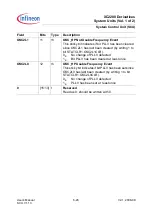
PRDY
5
rh
P-Divider Ready Status
0
B
Bit field PLLCON1.PDIV has been changed,
new K1 divider value not yet used.
1
B
The P-Divider operates with the value defined
in bit field PLLCON1.PDIV.
NRDY
6
rh
N-Divider Ready Status
0
B
Bit field PLLCON0.NDIV has been changed,
new K1 divider value not yet used.
1
B
The P-Divider operates with the value defined
in bit field PLLCON0.NDIV.
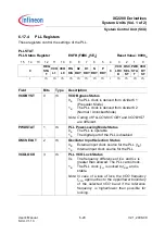
K1RDY
7
rh
K1-Divider Ready Status
0
B
Bit field PLLCON2.K1DIV has been changed,
new K1 divider value not yet used.
1
B
The K1-Divider operates with the value defined
in bit field PLLCON2.K1DIV.
K2RDY
8
rh
K2-Divider Ready Status
0
B
Bit field PLLCON3.K2DIV has been changed,
new K2 divider value not yet used.
1
B
The K2-Divider operates with the value defined
in bit field PLLCON3.K2DIV.
FINDIS
9
rh
Input Clock Disconnect Select Status
0
B
The VCO is connected to the reference clock
1
B
The VCO is disconnected from the reference
clock
Note: Software can control this bit by writing 1 to bits
SETFINDIS or CLRFINDIS in register
STATCLR1.
VCOL0
10
rh
VCO Lock Detection Lost Status
This sticky bit indicates if bit VCOLOCK has been
cleared since VCOL0 has last been cleared (by
writing 1 to bit STATCLR1.VCOL0CLR).
0
B
No falling edge detected
1
B
PLLV has been cleared at least once
(VCO lock was lost)
Field
Bits
Type
Description


