M
DSP
DIGITAL
POWER AMPLIFIER
Page
28
/
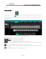
box, gain slider) are for adjusting the gain value of this channel.
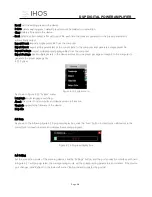
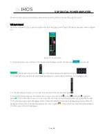
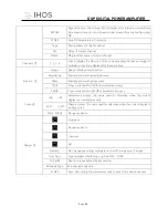
2. Among the function buttons, the buttons from top to bottom are: mute
, equalizer bypass , delay
, compressor
, limiter
r, polarity
, if the mute button is red, it is in mute state, and if the other buttons are green , It is the effective
state.
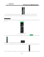
3. The channel grouping joint debugging situation shows the default 4 channel joint debugging grouping. When the
background color of the corresponding number box turns to yellow
, it means that this channel has been added to
the second group for joint debugging.
7.13 Channels link
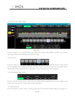
Click the joint adjustment button
between list of input and output channels shown in Figure 6.1, and the
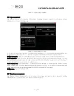
following Figure 7.10 channels link interface will pop up.
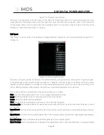
Figure 7.10 Channels link interface
As shown in the figure above, the three lists from left to right are divided into channel list, group list, and parameter list:
The channel list has listed all the channels that can be tuned together. After selecting the corresponding channel, click
the Add button
to move to the group list.
There are already 2 groups in the group list, directly select the corresponding group. If you add a channel to the channel
list, it will be directly divided into the selected group. If you want to remove the channel you want to remove, click Add
and press the remove button
below the button. It can be removed to the channel list.
The parameter list is the parameters that can be adjusted jointly in the grouping list. After checking, it means that when
several channels in the same group adjust the parameters, other channels will make the same adjustment at the same
time.

