M
DSP
DIGITAL
POWER AMPLIFIER
Page
9
/
37
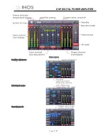
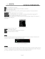
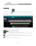
Figure 6.1
As shown in Figure 6.1, main screen all parts in yellow corresponding position as follows:
(1) Menu bar
(2) Scan button
(3) Setting button
(4) Link button
(5) Device list
(6) Module button
(7) Homepage monitor area
(8) Module function interface
(9) List of input and output channels
(10) IP address in this machine
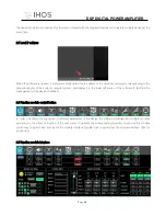
6.1 Initial interface
Device setting
2 3 4
5
7
6
10
8
9


