M
DSP
DIGITAL
POWER AMPLIFIER
Page
26
/
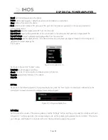
As shown above, you can control the polarity and mute setting of the corresponding output channel.
7.11 Input channel
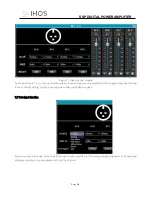
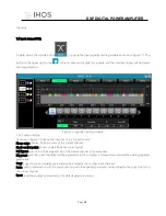
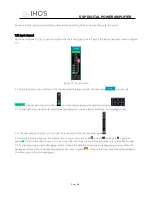
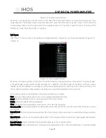
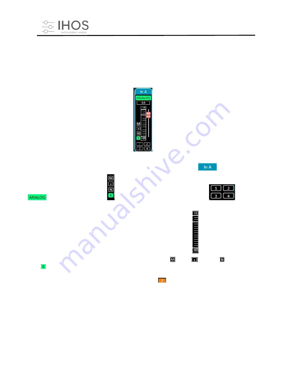
As shown in Figure 6.1, list of input and output channels homepage, the left part is the input channel as shown in Figure
7.9.
Figure 7.9 Input channel
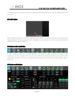
1. The contents from top to bottom in the input channel interface include: channel name
, input mode
, channel gain, function buttons
, and channel grouping joint adjustment situation
.
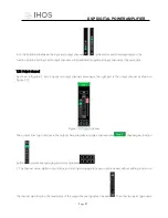
2. The channel name, input mode, and channel grouping can only be viewed, and there is no editing function.
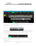
3. In the channel gain function, you can see the level status of the input channel signa
l.
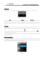
4. Among the function buttons, the buttons from top to bottom are: mute
, polarity
, noise gate , equalizer
bypass , if the mute button is red, it is in the mute state, and if the other buttons are green, it is in the effective state.
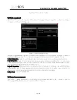
5. The channel grouping joint debugging situation shows the default 4 channel joint debugging grouping. When the
background color of the corresponding number box turns to yellow
, it means that this channel has been added to
the second group for joint debugging.


