M
DSP
DIGITAL
POWER AMPLIFIER
Page
10
/
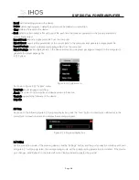
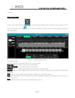
Figure 6.1.1
1.
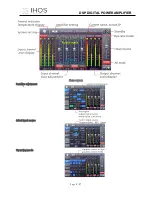
Showed in Figure 6.1.1, click
, the device can be switched of POWER ON or STANDBY, green means
POWER the ON state, yellow means STANDBY state.
2.
Click
, you can make the display screen and status light of the connected device flash, and you can quickly
find the connected device from the power amplifier device stack.
3.
Initial power on state can be selected.
,After selecting, it will be directly switched
to the selected state after the hard switch is turned on.
4.
Click the button in the frame to quickly switch the routing status. There are 4 options available: stereo, parallel, bridge,
and matrix.
6.1.1 Device info
1.
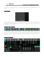
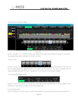
As shown in Figure 6.1.2, the device name, group, and IP can be modified in
the upper left corner of the initial interface, and then “device”-“devices”,
information can be changed according to actual needs.
2.
The device model and LINK ID cannot be changed. The LINK ID is the
corresponding ID when the host computer is connected to multiple devices:
3.
Preset name is the name of the currently used
preset.
Figure 6.1.2
6.1.2 Input setting


