M
DSP
DIGITAL
POWER AMPLIFIER
Page
19
/
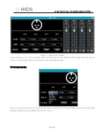
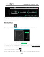
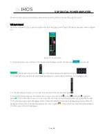
In the test signal generation setting, the three test signals can be set to generate the corresponding gain value of the test
signal. The switch button on the right side of each test signal can control whether the test signal is effective. Green is on,
red is off, and you can set frequency of sine wave.
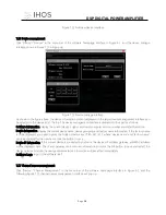
7.3 Input channel noise gate
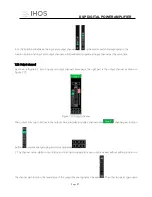
Double-click noise gate button
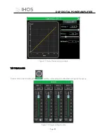
, the figure 7.2 below input channel noise gate setting module pops up.
Figure 7.2 input noise gate setting module
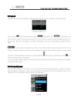
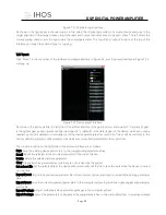
As shown in Figure 7.2 above, click the noise gate switch
in the upper right corner to turn on or off
the noise gate function of the channel input signal. The green is on, the red is off. The attack time, release time, and
threshold level are the parameter corresponding to the noise gate. You can drag the slide bar
or enter the corresponding value in the value box
.
When the noise gate function is turned on, the point
in the graph on the left can be dragged diagonally to adjust

