background image

This document is property of NIIGATA POWER SYSTEMS CO., LTD. It must be neither reproduced nor communicated nor published without permission.


SECTION 

 -  DISASSEMBLY AND REASSEMBLY 


4.4    FUEL INJECTION VALVES AND FUEL INJECTION 

PUMPS 


4-4-07


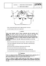
    - Remove the roller pin 

, and roller 


    - Measure the inner diameter of the roller, the outer diameter of the pin, and 


       the inner and outer diameters of the roller bushing 

.    Refer to the maximum 


       wear limits shown in Section 3.2 and replace any parts that exceed 


  the clearance limits.    If pitting or chipping is apparent on the roller wear 


 surface, install a new roller. 


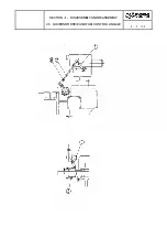
    - When the roller guide assembly is reassembled, recheck the dimension 'A' as 


 shown in Figure.    It should be the same as the original    measurement (plus 


       0.0, minus 0.1 mm) to insure that pump timing is not changed.    If the 


       measurement differs from the original (because of new parts installation), 


       the shim thickness should be changed as required to maintain the original 


    dimension. 


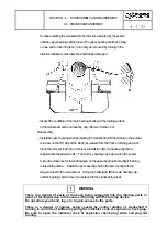
  Plunger Barrel Assembly 


    - With the plunger, the roller follower assembly, and the delivery valve 


 assembly removed, next remove the control rack 

  and the control sleeve

.   


 Remove the deflectors 

  and the locating screw 

.  The plunger 


 barrel 

  can now be removed and inspected. 


    - An adjusting mark is stamped on the plunger and barrel assembly to indicate 


 the start of injection.    If new parts are installed, review. 


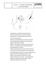
    - When reassembling the plunger assembly, install new o-rings 

 and   . 


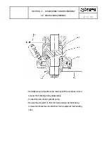
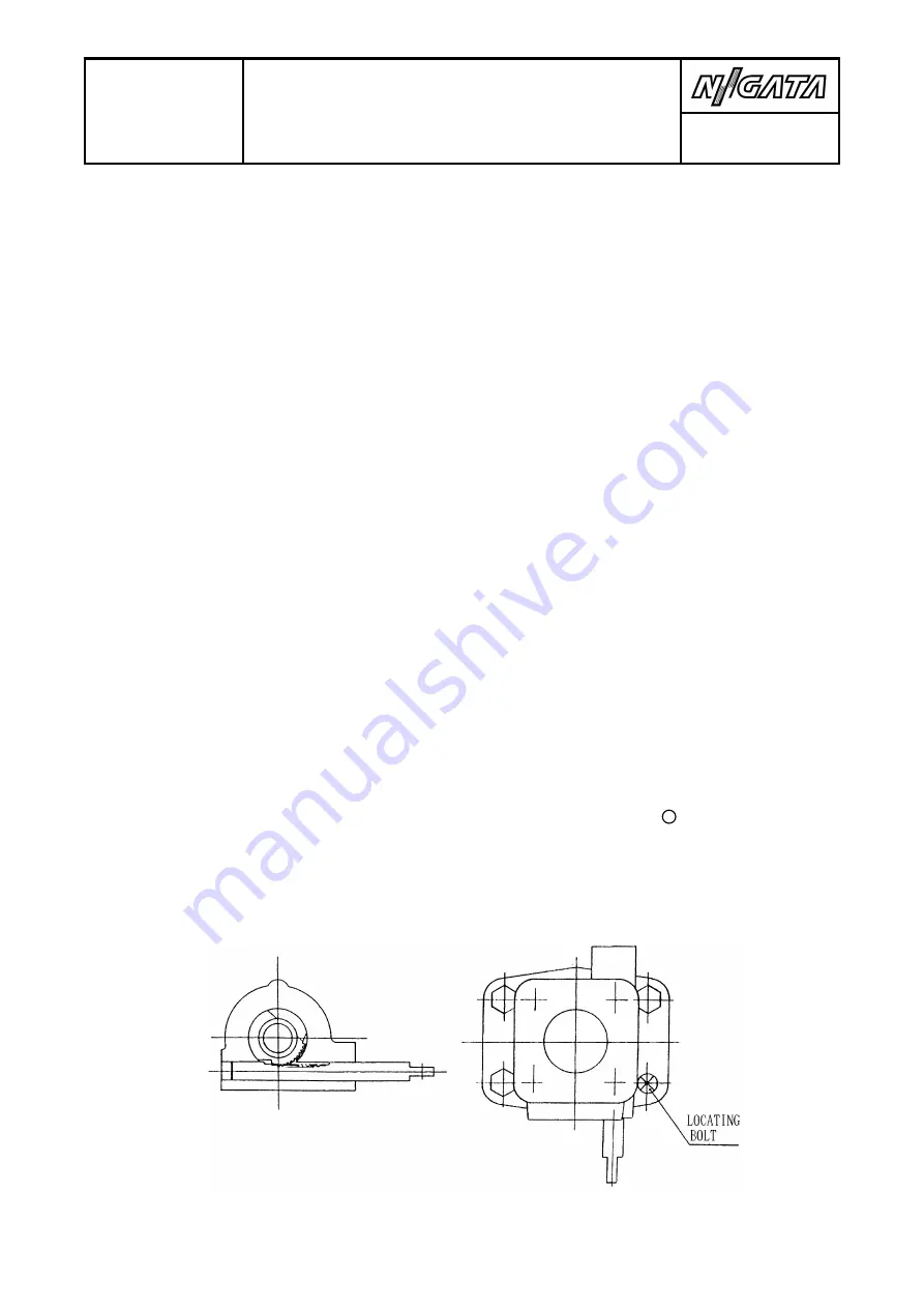
    Install the control sleeve 

 and rack 

, mating the end tooth of the 


 sleeve to the end tooth of the rack, as shown. 


21  

Содержание NIIGATA MG(L)26HLX

Страница 1: ...DOCUMENT No 2086X 50000D REMARKS 12 2021 INSTRUCTION MANUAL FOR NIIGATA DIESEL MODEL MG L 26HLX...

Страница 2: ......

Страница 3: ...manual only after reading this manual carefully to familiarize themselves with the contents In particular Safety Precautions of this manual shall be read carefully to have a good understanding of the...

Страница 4: ...when ordering parts when receiving parts and when mounting parts be sure to contact us 5 For details of ancillary equipment please refer to individual makers instruction manuals 6 Contents given in th...

Страница 5: ...of the knowledge of plant and equipment safety information and cautionary instructions Besides the above it is recommended to keep this manual near at hand so that the manual can be referred to at an...

Страница 6: ...and occurrence of serious physical damage are presumable Where possible danger of suffering from light or medium physical injuries and occurrence of physical damage are presumable Even such matters wh...

Страница 7: ...sageway Always try to keep clean such foothold places as floor surface foot plate etc that are made slippery and exposed to a danger of tumbling or falling if fouled with oil water or the like Make su...

Страница 8: ...sure that lifting outfits such as chain hook rope etc are free from abnormalities at any time and observe service criteria and permissible load Hang hooks on the proper positions and use stays necessa...

Страница 9: ...the handling work In the case of joint work also the weight should be limited to less than 20kg per person When handling refrigerants such as liquid nitrogen put on protective outfits for the preventi...

Страница 10: ...MS CO LTD It must be neither reproduced nor communicated nor published without permission Others Do not remodel the engine and plant equipment without our permission Should there be any indistinct poi...

Страница 11: ...s to avoid causing bolt looseness gasket deterioration and equipment and pipeline cracking 2 In cases of lubricating oil leakage from equipment and pipelines of lubricating oil line there is a danger...

Страница 12: ...ine running forthwith and take Preventive measures against leakage 3 Anti freeze 1 Keep away from the fire since anti freeze entails the danger of ignition to scald 1 Crankcase door 1 Where the engine...

Страница 13: ...access to the blow off nozzle 2 Cylinder safety valve 1 There are cases where scald is caused by the actuation of cylinder safety valve due to abnormal pressure rise inside the cylinder Do not gain a...

Страница 14: ...is a danger of fire hazard due to emission of flammable gas from battery Keep the surroundings of battery away from the fire 5 Engine room for gas engine 1 In cases of gas leakage from gas fuel pipeli...

Страница 15: ...cation 3 In cases where an alarm is given by the actuation of gas detector during the period of engine stop there is a danger of explosion Close the gas partition valve and turn OFF AC power supply Th...

Страница 16: ...tion Before turning ON power supply check if there are any abnormality in wire connections and peel off of covering 2 Electrical devices 1 Electrical devices such as various switches electrical govern...

Страница 17: ...y check if there are any abnormality in wire connections and peel off of covering 3 Ignition line wiring booster coil and high tension coil of gas engine entail the danger of electrifi cation due to h...

Страница 18: ...preventive agent inhibitor and anti freeze for use with cooling water line are poisonous to the human body Handle them carefully so that they will not come into eyes or come in contact with the body 3...

Страница 19: ...n the foot plate and shoes 2 Topside of engine 1 The topside of engine intake manifold air duct etc that is slippery in some cases entails the danger of tumbling and falling Do not step on their topsi...

Страница 20: ...as been confirmed 1 Flywheel 1 There is a danger of parts of the body being entangled into the flywheel area in the course of engine running Do not allow your hand leg etc to gain access to the area 2...

Страница 21: ...working in the inside and in the vicinity of the engine being entangled when turning the engine Carry out the turning operation only after making sure of freedom from danger 3 There is a danger of inj...

Страница 22: ...or legs being entangled during the course of grinding turning and drilling work Do not put on gloves 1 Moving parts of engine 1 There is a danger of hands or legs being pinched By the moving parts va...

Страница 23: ...ere between the inside and outside Take precautions so that your body will not be pinched 3 When installing disassembling reassembling 1 There is a danger of your hands being pinched by the gear and c...

Страница 24: ...droplets In case where high pressure oil droplets have come into your body through the skin then it is necessary to undergo forthwith specialist s diagnosis and surgical treatment 1 Engine 1 Since th...

Страница 25: ...over the skin Sampling work of cylinder internal pressure Cleaning of lubricating oil fuel oil filters When removing the caps of radiator and pressurized fresh water expansion tank 3 When checking by...

Страница 26: ...physical accidents due to failure of parts Unfailing control should be conducted on the basis of instruction manual or specifications 2 Disassembly work of spring section 1 When disassembling the spr...

Страница 27: ...to gain access to the range covered by oil droplets In case where high pressure oil droplets have come into your body through the skin then it is necessary to undergo forthwith specialist s diagnosis...

Страница 28: ...carry out the following items to prevent the erroneous start of the engine Disconnection of battery power source Capacitor discharge 2 There is a possible danger of physical accidents that may be cau...

Страница 29: ...ngine when gasoline or alcohol is used as a fuel or mixed into fuel oil Be sure to use the specified fuel oil only 1 Electrical governor remote controller 1 There is a danger of critical accidents ari...

Страница 30: ...hen handling fuel oil lubricating oil cool ing water and inhibitor and anti freeze solution In course of washing work In course of fuel injection valve injection test When handling battery electrolyte...

Страница 31: ...ead 1 Work necessitating protective mask 1 Put on protective masks since the following items of work are in danger of adverse effect upon the health due to inhalation of deleterious mist or dust In co...

Страница 32: ...your hands except for the case of special work 2 During machining work 1 There is a danger of entanglement in the course of grinding turning and drilling work Do not put on any gloves 1 Chemicals han...

Страница 33: ...1 Fire extinguisher 1 In carrying out the work inside the engine room and enclosure there is a danger of flammable liquid etc being ignited by welding or electric sparks Be sure to make a fire exting...

Страница 34: ......

Страница 35: ...P AFTER A NORMAL SHUTDOWN 2 2 SPECIAL INSTRUCTIONS FOR HEAVY FUEL OPERATION 2 3 NORMAL SHUTDOWN PROCEDURE 2 4 STARTING AFTER ENGINE OVERHAUL OR EXTENDED SHUTDOWN 2 5 RUN IN PROCEDURE AFTER MAJOR OVERH...

Страница 36: ...ONNECTING ROD 4 3 CYLINDER LINERS 4 4 FUEL INJECTION VALVE AND FUEL INJECTION PUMPS 4 5 GOVERNER DRIVE AND FUEL CONTROL LINKAGE 4 6 CRANKCASE ASSEMBLY 4 7 CRANKSHAFT 4 8 CAMSHAFT AND TIMING GEAR TRAIN...

Страница 37: ...m 9 806 65 J 1 J 0 101 972 kgf m 1 kcal 4 186 8 kJ 1 kJ 0 238 846 kcal Power 1 PS 0 735 499 kW 632 415 kcal h 1 kcal h 1 163 kW 1 581 24 PS 1 kW 1 359 622 PS 859 845 2 kcal h Specific fuel consumption...

Страница 38: ......

Страница 39: ...CO LTD It must be neither reproduced nor communicated nor published without permission S E C T I O N O U T L I N E CONTENTS SECTION 1 OUTLINE 1 1 GENERAL SPECIFICATIONS 1 2 FUEL OIL SPECIFICATIONS 1 3...

Страница 40: ......

Страница 41: ...ke mm 350 Compression Ratio 13 0 Max Output See the final document Rated speed See the final document Max Combustion Pressure MPa 14 71 Direction of Rotation Clockwise or Counterclockwise depending up...

Страница 42: ...rated speed and load Lubricating oil engine inlet Normal operating range 60 70 Alarm setting on 75 off 65 Trip setting on 80 off 70 Jacket water coolant Measured at engine outlet Normal operating ran...

Страница 43: ...bricating oil measured at inlet to engine Normal operating range 0 35 0 60 0 50 0 60 Alarm on 0 20 0 45 Trip on 0 15 0 40 Jacket water measured at inlet to engine Normal operating range 0 28 0 36 0 28...

Страница 44: ...GENERAL SPECIFICATIONS Starting air reservoir pressure Normal operating pressure 1 77 2 94 2 16 2 94 Alarm on 1 47 1 77 Turbocharger lube oil inlet For TPS Normal operating pressure 0 20 0 45 0 20 0...

Страница 45: ...ctory Modified to provide for jacket water cooling of the injectors modified piston rings heat treated top piston ring groove modified valve rotators additional cooling water passages around the exhau...

Страница 46: ...CARBON WT WT WT A LIGHT 0 87 9 5 0 1 0 2 01 B LIGHT 0 90 9 5 1 0 0 2 01 C1 INT 0 90 30 1 8 1 5 02 C2 INT 0 97 30 180 0 3 10 05 1 8 D1 HEAVY 0 97 30 180 1 8 10 05 3 0 D2 HEAVY 0 99 180 380 1 5 12 10 4...

Страница 47: ...and solids from the fuel oil before it enters the fuel pump Excess moisture not only reduces the calorific value heat energy of the fuel but can cause rust and deposit problems on internal engine comp...

Страница 48: ...FUEL OIL SPECIFICATIONS 3 Use of Light Fuel Oil No2 Diesel Light fuel should always be used in the following situations for run in operation after engine overhaul when starting and stopping the engin...

Страница 49: ...cating Oil 1 Viscosity Lubricating oil of SAE40 viscosity must be used for this engine WARNING Multi viscosity oils eg 15W 40 are not to be used 2 Base Number The total base number TBN provides a rela...

Страница 50: ...30 30 40 40 MOBIL MOBILGARD 412 15 MOBILGARD 424 30 MOBILGARD 442 40 POWERGARD 42 12 POWERGARD 2040 20 POWERGARD 3040 30 ESSO EXXMAR 12TP40 12 EXXMAR 24TP40 24 EXXMAR 30TP40 30 EXXMAR 40TP40 40 STAMA...

Страница 51: ...ts Traces of moisture are inevitable but total moisture content should not exceed 0 3 by volume Centrifuging is desirable to keep water content to a minimum If the water content exceeds 0 5 by volume...

Страница 52: ...cumulate hours rapidly it is also recommended that on site analysis of the oil condition be conducted every 100 hours Lubricating oil can deteriorate rapidly under certain conditions and the on site t...

Страница 53: ...ant or a sea water raw water circuit The desired water characteristics for closed circuits include should be clear no sediments less than 200 ppm silica pH value 7 0 or higher chlorine ion concentrati...

Страница 54: ...are available for satisfying this C O D value To dilute the water with water of a suitable volume To blow air in To oxidize the water by adding a suitable oxidizer sodium hypochlorite etc 2 Caution in...

Страница 55: ...ed by central and local governments which may differ from one country to another Study such regulations and consult inhibitor manufacturer when disposing of waste water 3 Others If air enters the cool...

Страница 56: ...INDUSTRIES LTD 8500 12000 HIMOL AM 5 1000 3000 HIMOL L 10 TAIHO INDUSTRIES CO LTD 8000 12000 INHIBITOR Nitrite NEOS PN 106 PN 106S NEOS CORPORATION 106 2000 3000 106S 8000 12000 APOLLO LONG LIFE COOL...

Страница 57: ...water treatment agent together with anti freeze of this type but water treatment agent of chromate type nannot be used together with anti freeze of this type The following figure indicates the follow...

Страница 58: ...e at the time of supply of water into the cooling system that the cooling system is free from contamination There are cases where the concentration of the treating agent in the cooling water gradually...

Страница 59: ...TARTING AND WARMUP AFTER A NORMAL SHUTDOWN 2 2 SPECIAL INSTRUCTIONS FOR HEAVY FUEL OPERATION 2 3 NORMAL SHUTDOWN PROCEDURE 2 4 STARTING AFTER ENGINE OVERHAUL OR EXTENDED SHUTDOWN 2 5 RUN IN PROCEDURE...

Страница 60: ......

Страница 61: ...by the actuation of crankcase safety valve due to abnormal pressure rise inside the crankcase Do not gain access to the blow off nozzle There are cases where scald is caused by the actuation of cylind...

Страница 62: ...he main valve of starting air tank outlet Release the residual pressure remaining Inside the starting air pipeline Between the starting air tank to the engine CAUTION Since there are many hot parts in...

Страница 63: ...the above checks the lube oil priming pump should be started the indicator cocks on all cylinders should be opened and the engine should be rotated with the turning device for 3 or 4 complete revolut...

Страница 64: ...ylinders are firing normally These temperatures should rise 70 100 in about one minute If an individual cylinder is significantly cooler than the others the fuel injector of that cylinder should be ch...

Страница 65: ...before the switch to heavy fuel is made The engine should be operated on LIGHT fuel at lightly loaded conditions less than 1 3 of rated load Operation at light load with heavy fuel can cause excessiv...

Страница 66: ......

Страница 67: ...to make sure the governor lever is in the STOP position b Open the indicator cocks for each cylinder WARNING There is a danger of injuries being caused by contra rotation of crankshaft if turning is...

Страница 68: ......

Страница 69: ...of work being in danger of injury to eyes When handling fuel oil lubricating oil cooling water and inhibitor and anti freeze solution In course of washing work In course of fuel injection valve inject...

Страница 70: ...nspection covers and check for oil flow to the crankshaft bearings and pistons Remove the valve covers and check for oil flow to the cam bearings cam followers and to the intake and exhaust rocker arm...

Страница 71: ...f your hands being pinched by the gear and cam roller of the engine Never insert your hands in the course of turning Open the cylinder indicator cocks Rotate the crankshaft in the normal direction slo...

Страница 72: ...ing out turning There is a danger of your hands being pinched by the gear and cam roller of the engine Never insert your hands in the course of turning The engine should turn over freely at this point...

Страница 73: ...stop due to abnormal heat generation being detected inside the engine room there is a danger of explosion if crankcase door is allowed to open forthwith Open the door after the lapse of a cooling peri...

Страница 74: ...e heat build up Shut the engine down immediately if any problems are noted Check all system pressures and operating temperatures while the engine is running to insure they are within normal operating...

Страница 75: ...ld To prevent this first allow your finger to approach to the work and make sure that it is not hot followed by conducting the check by finger touch If the work is hot do not conduct the check by fing...

Страница 76: ...w additions should be made if possible when the engine has cooled If the engine is equipped with an external system that maintains the oil level it should be checked to insure that it is working corre...

Страница 77: ...follows marine applications The high temperature circuit is a closed system with treated water The low temperature circuit may operate with either treated water from a closed system or from sea water...

Страница 78: ...5 Low temperature cooling circuit As above a pressure gage is installed at the pump discharge Normal values for both temperature and pressure are given in the table in Section 1 1 These values should...

Страница 79: ...the result of a malfunctioning injector The valve should be removed and bench checked as outlined in the Maintenance section Operate the emergency stop device every month and confirm that it operates...

Страница 80: ......

Страница 81: ...5 MPa 0 25 0 35 MPa C oil 380mm2 s 0 45 0 55 MPa 0 45 0 55 MPa Minimum value 0 05 MPa 0 05 MPa Lubricating Oil System rated speed Pressure at engine inlet Standard value 0 35 0 60 MPa 0 50 0 60 MPa Mi...

Страница 82: ......

Страница 83: ...procedures for a Normal Shutdown listed in Section 2 3 Lube oil system Completely drain the lube oil system including the crankcase filters lines etc It is recommended that the system be filled with...

Страница 84: ...nlet and outlet ports are sealed to prevent dirt and moisture from entering the system Intake and exhaust systems Place silica gel in the intake air duct and seal the duct as required to keep out abou...

Страница 85: ...n pressure is useful for oil control of piston rings The liner contact pressure is increased by the back pressure of rings But in low load operation this function does not work usefully so oil rises t...

Страница 86: ......

Страница 87: ...produced nor communicated nor published without permission S E C T I O N M A I N T E N A N C E CONTENTS S E C T I O N M A I N T E N A N C E 3 1 GENERAL 3 2 CLEARANCE AND WEAR TABLE 3 3 TABLE OF TORQUE...

Страница 88: ......

Страница 89: ...intake exhaust valve grinding work There is a danger of injury to your hands during the work inside the engine room and enclosure Be sure to put on gloves for the protection of your hands except for...

Страница 90: ...Position of observer 2 Rotation direction The observer denotes the two rotational directions of the crankshaft of the engine as clockwise and counter clockwise as following figure Fig Rotation directi...

Страница 91: ...d engine Be sure to carry out the following items to prevent the erroneous start of the engine Close the main valve of starting air tank outlet Release the residual pressure remaining Inside the start...

Страница 92: ...er major engine repairs be certain to run the lubricating oil priming pump for several minutes before attempting to start the engine Starting without the necessary lubrication to critical parts can ca...

Страница 93: ...ey are being worked on Do not rely on jacks or hoists to support the work Wear protective glasses and safety shoes when working Do not wear loose fitting or torn clothing that could become entangled i...

Страница 94: ......

Страница 95: ...Limit beyond which the use of the part is hazardous rework or immediate rejection NOTE 1 A component reaching LA limit may be used on 2 A component more worn than LA may be safely used on but not for...

Страница 96: ...e 33 0 MPa Adjust with injection test pump 2 Crankshaft main bearing Inner diameter Clearance Crank shaft bearing D1 C 0 22 210 0 16 0 16 0 25 0 35 Replace when the copper lead coating is visible on m...

Страница 97: ...haft undersize measurements Crankpin M1 M2 Crankjournal M1 M2 194 75 0 0 03 194 5 0 0 03 209 75 0 0 03 209 5 0 0 03 5 Crank deflection dv Each slows Flywheel side slow dn dv dV dn 0 04 0 01 0 07 0 07...

Страница 98: ...e 1st compression ring 2nd compression ring 3rd compression ring oil ring Ring width 1st compression ring 2nd compression ring 3rd compression ring oil ring Groove height 1st compression ring 2nd comp...

Страница 99: ...l ring 1st compression ring 2nd compression ring 3rd compression ring oil ring T a 0 15 8 5 0 15 0 15 9 0 0 15 0 15 9 0 0 15 0 15 5 5 0 15 1 4 1 7 1 0 1 3 1 1 1 3 0 8 1 1 3 5 3 5 4 4 Over size of the...

Страница 100: ...Bearing inner diameter big end Piston pin bushing inner diameter Piston pin to bushing clearance OV d2 D2 d2 0 14 0 22 0 19 195 0 14 0 13 105 0 09 0 11 0 17 0 05 0 35 0 3 Replacement when the copper...

Страница 101: ...cklash Crank gear Gear idle 1 Gear idle 1 Cam gear Cam gear Gear governor Gear idle 1 Idle gear CWP Idle gear CWP Gear CWP Crank gear Gear idle 2 Gear idle 2 Idle gear LOP Idle gear LOP Gear SWP Idle...

Страница 102: ...Angular clearance C 0 03 0 06 0 5 13 Valve gear Tappet bore diameter Tappet shaft diameter Clearance Tappet Shaft Roller bushing bore diameter Roller pin diameter Clearance Roller pin Bush Roller inn...

Страница 103: ...ance Shaft Bush CROSSHEAD bore diameter Crosshead guide outer diameter Clearance cross headguide to bore C1 C2 D1 d1 D1 d1 D2 d2 D2 d2 0 5 0 5 0 08 55 0 02 0 03 55 0 05 0 13 0 17 0 02 26 0 0 02 26 0 0...

Страница 104: ...Gear shaft diameter Clearance shaft Bushing D1 d1 D1 d1 0 05 45 0 0 05 45 0 08 0 05 0 13 0 2 17 Water pump Clearance Impeller Liner ring C 0 15 0 30 0 6 18 Damper Dimension Metal side case T 0 05 0 1...

Страница 105: ...ts positively refer to section 3 3 3 Full care must be taken at the time of tightening paying full consideration to the following 1 Clean the threads and seat surface of bolts and nuts fully and confi...

Страница 106: ...initial torque and angle of second stage are described in section 3 3 3 Inspection of the angle is as follows If the angle is a multiple of 30 Countermark are stamped on screws or nuts directly Other...

Страница 107: ......

Страница 108: ......

Страница 109: ...in bearing cap 6 47 4 Crankshaft ass y 1 1465 With balance weights 5 Flywheel 1 371 With bolts 6 Cylinder block 1 5040 With stud bolts and bearings 7 Cylinder liner 6 101 8 Camshaft ass y 1 170 With d...

Страница 110: ......

Страница 111: ...or explosion check plug when carrying out turning There is a danger of your hands being pinched by the gear and cam roller of the engine Never insert your hands in the course of turning Any negligenc...

Страница 112: ...oil cooling water and inhibitor and anti freeze solution In course of washing work In course of fuel injection valve injection test When handling battery electrolyte In course of grinding work In cou...

Страница 113: ...rarely S N Check if required Every day Check if required Once per week A1 Every 100 hours Every 1 3 months A2 Every 500 hours B C Every 1250 hours or every 3 months Every 2500 hours or every 6 months...

Страница 114: ...n of fuel injection valve starting air valve starting air distributor and filter nseed to be carried out every year for safety Inspection S Following inspection have to carried out before normal inspe...

Страница 115: ...t engine inlet Read pressure of turbo charger lub oil in case external oil supply Check oil level of turbo charger for NHP type T C Fuel oil system Level check on fuel tank Read pressure drop at fuel...

Страница 116: ...ter Remove Sludge from filter and check any abnormality Overhaul filter when pressure difference exceeds 2times of normal value Clean centrifuge filter if equipped Overhaul rotor ass y Remove sludge a...

Страница 117: ...ve Injection test by means of test pump at first 500hours and maintenance B afterwards Fuel control lay shaft governor linkage Check smooth function Emergency stop device Check to operate normally eve...

Страница 118: ...ure valve guide wear and check any hard mark Crank shaft deflection measurement Cam shaft Cam and roller inspection through inspection doors Renewal governor oil Flexible coupling if equipped Check ti...

Страница 119: ...eck on piston ring Measure diameter of piston pin Cylinder linear Check inner surface Measure bore diameter and make deglazing Connecting rod inspection Crank pin bolts Piston pin bush Big end bearing...

Страница 120: ...lace mechanical seal and oil seal Replace ball bearings Check pinion Manual of geislinger coupling Inspection E Interval 15 000 hours No Maintenance work reference E 01 E 02 E 03 E 04 Cylinder head Re...

Страница 121: ...rings Fuel injection pump Replace delivery valve Check plunger spring Overhaul of flexible coupling if equipped Cleaning of lub oil sump tank if necessary Overhaul governor at specialized shop Overha...

Страница 122: ...mshaft Visual inspection on cam and bearing Visual inspection on camshaft bearing shell Crankcase Check inside and outside of crankcase Gear train Overhaul all gears Check cracks on the gears by dye p...

Страница 123: ...injection pump Pump overhauling at specialized shop Replace plunger ass y Governor driving device Check gears Measure backlash Replace oil seals Replace ball bearings Fuel feed pump Replace coupling r...

Страница 124: ...wo service men and a assistant Operation carried out by three service men Operation carried out by specialized shop Maintenance hours Maintenance work and inspection part No Lub oil system N 01 Daily...

Страница 125: ...DULE Maintenance hours Maintenance work and inspection part No Collect lub oil A2 01 Every 500 hours sample for analysis Check engine A2 01 Every 100 hours performance data Renewal of lub oil B 01 Cra...

Страница 126: ...intenance work and inspection part No Valve gear F 08 Cylinder head intake and exhaust valve heavy fuel operation B 04 C 01 E 01 F 07 Cylinder head intake and exhaust valve MDO operation B 04 D 01 E 0...

Страница 127: ...eed pump and driving device D 16 F 11 Exhaust manifold F 13 Turbo charger A1 05 Every 100 hours Refer to the A2 03 Every 500 hours manual of turbo charger C 11 D 10 Air cooler C 12 D 11 Torsional vibr...

Страница 128: ...0 4 8 12 16 20 24 28 32 36 40 Check and reconditioning intake exhaust valve and valve seat Check and replace fuel injection valve Inspection and cleaning filters Overhaul turbo charger and replace bal...

Страница 129: ...e ball bearing of idle gear shaft Replace intake and exhaust valve spring Replace main bearing shell Replace thrust collar of crank case Overhaul and inspection safety valve of cylinder head Remove an...

Страница 130: ......

Страница 131: ...TION 4 DISASSEMBLY AND REASSEMBLY 4 1 CYLINDER HEAD AND VALVE MECHANISM 4 2 PISTON AND CONNECTING ROD 4 3 CYLINDER LINER 4 4 FUEL INJECTION VALVE AND FUEL INJECTION PUMP 4 5 GOVERNER DRIVE AND FUEL CO...

Страница 132: ......

Страница 133: ...When using hydraulic tools or when conducting the fuel injection valve injection test high pressure fluid will gush out leading to the danger of injuries Never allow your body to gain access to the r...

Страница 134: ...he turning device Do not allow your hand leg etc to gain access to the parts There is a danger of injuries being caused by contra rotation of crankshaft if turning is carried out without opening the i...

Страница 135: ...and jacks A3 A4 over two diagonally opposite cylinder head studs Connect the lines from the jack A12 to the hydraulic pump Open the valve of the hydraulic pump to drain the jacks Then loosen the nuts...

Страница 136: ...Disassembly of the Cylinder Head Once the cylinder head stud nuts have been removed the inlet and exhaust manifolds can be disconnected and the heads remover by using a suitable sling and eye bolts Th...

Страница 137: ...l Tighten the nut enough to compress the valve springs and remove the keepers from the valve retainers Remove the tool remove the retainers and position the cylinder head on its side to remove the val...

Страница 138: ...ussian Blue as outlined above If new inserts are necessary make certain that the bore is clean and that the seat is pressed completely to the bottom of its bore Contact pattern should be rechecked aft...

Страница 139: ...ible disassemble the parts as follows Remove the rocker arm support and rocker arms Remove the push rods Loosen the bolts that secure the tappet arm shaft and remove the tappet arms and shaft Any bent...

Страница 140: ...the cylinder head are plugged To remove the starting valves disconnect the air line to the valve remove bolts and lift the valve from the cylinder head To disassemble the valve remove the cover CAUTOI...

Страница 141: ...he piston is slightly below the top dead center position Fill the gap between the top of the piston and the cylinder liner with grease to prevent debris from dropping into the gap and clean the carbon...

Страница 142: ...ngs and replace any that show damage The rings should move freely in the ring grooves If a buildup of carbon or gum is visible in the bottoms of the grooves the rings should be removed and the grooves...

Страница 143: ...d the bearing cap using Prussian Blue or equivalent Each face should contact over 80 of its area If the crankshaft has been reground there are two options for oversize bearings as shown in Section 3 2...

Страница 144: ...o that the rod journal is about 30 degrees from top dead center toward the camshaft side of the engine WARNING There is a danger of parts of the body being entangled into the rotating parts or gears o...

Страница 145: ...g shell in the rod cap install the rod cap coat the rod cap bolts with Molykote or similar lubricant and loosely install the bolts Make certain that the cylinder number stamped on the rod cap and on e...

Страница 146: ...ld first be installed and torqued in the rod assembly without the bearings installed Coat the threads with Molykote or similar lubricant tighten to the specified value minus 10 degrees loosen and repe...

Страница 147: ...iner flange and the top surface of the block O ring seals are used on the OD of the liner to seal the water passages in the block 4 3 2 Visual Inspection After removing the cylinder head and the pisto...

Страница 148: ...4 3 3 Measurement of Liner Bore After deglazing measure the liner bore using a dial indicator or micrometer Measuring points are described in the Clearance and Wear Table If the measured values excee...

Страница 149: ...nto service a descaling agent should be added to the cooling system to remove scale from the rest of the system DO NOT use acid solutions for descaling Dye Penetration Test Cylinder liner flanges shou...

Страница 150: ...ND REASSEMBLY 4 3 CYLINDER LINER Coat THREE BOND 1107 or equivalent on the bottom surface of the liner flange Reinstall the liners using the proper tools as shown below Make sure that the liner is fir...

Страница 151: ...your body through the skin then it is necessary to undergo forthwith specialist s diagnosis and surgical treatment Apply hydraulic pressure only after making sure that joints are securely connected Be...

Страница 152: ...ltered fuel is used for the testing Once the air has been bled from the system the valve opening pressure can be checked Increase the pressure to 27 0 MPa the nozzle should remain dry valve should not...

Страница 153: ...allow your body to gain access to the range covered by oil droplets In case where high pressure oil droplets have come into your body through the skin then it is necessary to undergo forthwith special...

Страница 154: ...e Needle seats can be lapped with lube oil only lapping compound should never be used If lapping with oil fails to correct a leakage problem a new nozzle should be installed Reassembly Reinstall the n...

Страница 155: ...s of the following main parts Delivery valve assembly and A plunger with a helix cut groove that meters the amount of fuel injected each stroke Plunger barrel Fuel control rack Rack control sleeve Cam...

Страница 156: ...alls and springs If any damage is apparent install new parts and reassemble using a new o ring Torque the bolts to the values shown in the Tightening Table Section 3 3 of this manual Remove and inspec...

Страница 157: ...in Figure It should be the same as the original measurement plus 0 0 minus 0 1 mm to insure that pump timing is not changed If the measurement differs from the original because of new parts installat...

Страница 158: ...inal new location This location should normally be satisfactory but should be checked as follows Apply Prussian Blue to the pump roller and rotate the crankshaft manually for two revolutions Inspect t...

Страница 159: ...ear which in turn drives input gears and This section describes the removal and installation of the governor the rack control linkage and the inspection of the governor gear drive mechanism It does no...

Страница 160: ...nd spacer and Remove the control lever bracket by removing bolts and remove the driveshaft Remove the shaft bearings Visually inspect the condition of all bearings and the condition of the drive gear...

Страница 161: ...ally actuating the lay shaft Make certain that full rack stroke is obtained and that the rack does not bind in any position 4 5 5 Adjustment of governor control linkage The governor is connected to th...

Страница 162: ...ument is property of NIIGATA POWER SYSTEMS CO LTD It must be neither reproduced nor communicated nor published without permission SECTION DISASSEMBLY AND REASSEMBLY 4 5 GOVERNOR DRIVE AND FUEL CONTROL...

Страница 163: ...into the sump is heavy enough that the oil appears milky a major leak is indicated and the engine should not be put back into service into the source is located and repaired When disassembling the mai...

Страница 164: ...overlay They are secured both vertically and laterally in the block Lubricating oil is provided to the bearings through internal ports in the block The rear No 1 main bearings includes the crankshaft...

Страница 165: ...TION DISASSEMBLY AND REASSEMBLY 4 6 CRANKCASE ASSEMBLY Hand tighten nut A5 with bar A4 then back off the nut about 1 4 turn to keep it from binding during disassembly Connect the jacks to the hydrauli...

Страница 166: ...joints are securely connected Release the hydraulic pressure and remove the jacks Attach the hydraulic pump now to the small bottle jack and position the jack underneath the main bearing cap to suppo...

Страница 167: ...t or timing gear end Insert the removal tool in the oil hole and install the dummy bearing cap that is supplied with the special tools The dummy bearing cap has a slot in the center to provide clearan...

Страница 168: ...ight use Molykote or similar lubricant on the studs Tighten the LH side bolt as viewed from the front or timing gear end to 245 N m Note that this is only about half the final torque value it will be...

Страница 169: ...r on the flywheel face or crankshaft hub Set the dial indicator to 0 and observe the displacement as the crankshaft is barred toward the rear of the engine If the end play exceeds the settled value ne...

Страница 170: ......

Страница 171: ...ommended at other settled intervals Section 3 2 During these inspections the condition of the crankshaft journals should also be noted if serious wear or scuffing is apparent complete measurements sho...

Страница 172: ...e body being entangled into the rotating parts or gears of turning device in the course of turning with the turning device Do not allow your hand leg etc to gain access to the parts There is a danger...

Страница 173: ...another it generally indicates a problem with the engine foundation The cause should be determined and corrected as soon as possible Crankshaft Journal Inspection The rod and main bearing journals sho...

Страница 174: ......

Страница 175: ...ly inspected by removing the inspection covers on the side of the block Unless damage is apparent there will normally be no need to remove the camshaft from the block until the scheduled settled inter...

Страница 176: ...document is property of NIIGATA POWER SYSTEMS CO LTD It must be neither reproduced nor communicated nor published without permission SECTION DISASSEMBLY AND REASSEMBLY 4 8 CAMSHAFT AND TIMING GEAR TR...

Страница 177: ...en separated into two section for removal insert the first section into the block until the coupling joint is just outside the block bolt the two sections together to insure proper alignment and slide...

Страница 178: ...xceeds the settled valve a new thrust bearing should be installed Measure the backlash between the cam gear and the idler gear with a dial indicator The backlash should not exceed the settled value Id...

Страница 179: ...age Complete the reassembly in the reverse order of disassembly Lube Oil Pump Idler Gear Bearings The lube oil pump idler gear can be removed as follows Remove the housing bolt then support the gear b...

Страница 180: ...the course of turning CAUTION The reference cylinder to be used when adjusting timing will always be the cylinder that is located to the timing gear The camshaft idler gear and camshaft drive gear mus...

Страница 181: ...gine camshaft and is mounted externally at the rear of the engine The distributor is connected by air lines to the individual cylinders As shown by the sketch the principal parts of the distributor ar...

Страница 182: ...engine Close the main air supply valve Remove the air supply line to the distributor and remove the cover Remove the rotor by using two M6 bolts in the puller holes that are provided Clean the rotor...

Страница 183: ...d disassemble the pump Drain the cooling system and remove the pump from the engine Remove the impeller housing Loosen the impeller retaining nut and remove the impeller withdrawing it carefully so th...

Страница 184: ...run in sleeve type bushings Disassembly Remove the pump from the engine Remove the drive gear retaining nut and the drive gear and Remove the front and rear covers and Remove the drive gear and driven...

Страница 185: ...side cover were removed pull out the springs and inspect them Remove the key and circular leaf springs by the half number of them After inspection and reassembly remove the remainder If deformation or...

Страница 186: ......

Страница 187: ...either reproduced nor communicated nor published without permission S E C T I O N M A I N T E N A N C E CONTENTS SECTION 5 TROUBLE SHOOTING 5 1 BEFORE DETECTING THE CAUSE OF TROUBLE 5 2 TROUBLES BEFOR...

Страница 188: ......

Страница 189: ...n access to rotating parts and moving parts There is a possible danger of physical accidents that may be caused when the engine is started by mistake during the inspection and repair of the battery st...

Страница 190: ...n to the jumping direction of parts so that the body will be kept away from the jumping direction When using hydraulic tools or when conducting the fuel injection valve injection test high pressure fl...

Страница 191: ...except special troubles If any slight abnormality should be observed check the related parts and minimize the trouble 2 Before starting operation Before starting operation keep the following points in...

Страница 192: ......

Страница 193: ...2 Water flows out of indicator cock 1 Water is condensed in air cooler Check for presence of moisture in the intake manifold 2 Entry of rain water through exhaust manifold Check for accumulation of wa...

Страница 194: ...leakage in lub oil cooler Check lub oil cooler 3 Entry of water of a minor volume into lub oil due to condensation when oil temperature is extremely low Check if thermostat is normally operating 4 Ent...

Страница 195: ...starting valve of cylinder located in starting position Elevate the pressure to 2 94 MPa Open the starting air valve Check the distributor Refer to 4 9 Check the starting valve Refer to 4 9 2 If equi...

Страница 196: ...4 Engine stalls after normal start 1 Malfunction of safety device Check if the safety device normally operates 2 Obstruction to starting by engine s abnormality stopping device Check the operation pan...

Страница 197: ...use Remedy 5 4 1 Abnormal noise 1 Abnormal noise which accompany combustion If noise stops when fuel injection is discontinued a Gas leakage from cylinder head joint b Gas leakage from exhaust flanges...

Страница 198: ...ct pistons connecting rods and turbine side of turbo charger 5 4 2 Smoke emission 1 Color of exhaust smoke is black a Insufficient feed air pressure b Unsuitable fuel valve opening pressure or faulty...

Страница 199: ...s a possibility of occurrence of explosion do not immediately open inspection doors after the engine has stopped Wait for about 15 minutes before opening inspection door a Tactually check the followin...

Страница 200: ...of water in fuel Drain water out of the fuel service tank 3 Operation of overspeed stopping device Find out the cause for operation and then reset the overspeed stopping device Caution If the overspee...

Страница 201: ...d Incomplete fuel feed Check the filter for plugging Refer to Items 5 3 2 5 3 3 Check for overloaded running 2 Intake exhaust valves are stuck Remove cylinder head covers and inspect failed intake exh...

Страница 202: ...nditions b Replace fuel valves c Quickly take necessary measure so that the trouble will not reach fuel valves 2 Elevated exhaust gas temperature a Unsuitable load b Faulty cooling of suction air c Ex...

Страница 203: ...ulator valve kept open a Check pressure gauge and its joint b Check differential pressure of the filter when the differential pressure becomes two times of normal value c Check the pressure regulator...

Страница 204: ...g water a Faulty cooling water thermostat b Shortage of low temperature cooling water flow rate c Priming water was not supplied to cooling water pump d Failed cooling water pump a Replace faulty sens...

Отзывы: