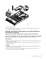


6.
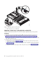
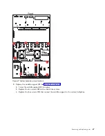
Pressing the latch release on the connector, disconnect the power switch cable (B) from the system
backplane. See Figure 56.
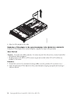
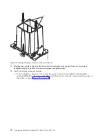
7.
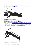
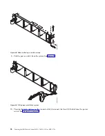
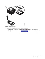
Remove the rack installation support from the side of the system. See Figure 57.
8.
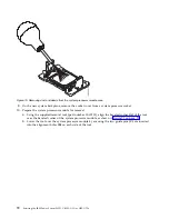
Remove the top and side screws from the power switch. See Figure 58 on page 58.
Figure 56. Removing the front USB cable and the power switch cable from the system backplane and disk drive fan
card
Figure 57. Removing the rack installation support
Removing and replacing parts
57
Содержание S822LC
Страница 1: ...Power Systems Servicing the IBM Power System S822LC 8335 GCA or 8335 GTA IBM...
Страница 2: ......
Страница 3: ...Power Systems Servicing the IBM Power System S822LC 8335 GCA or 8335 GTA IBM...
Страница 16: ...xiv Servicing the IBM Power System S822LC 8335 GCA or 8335 GTA...
Страница 134: ...118 Servicing the IBM Power System S822LC 8335 GCA or 8335 GTA...
Страница 145: ...Notices 129...
Страница 146: ...IBM Printed in USA...


