


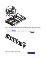


5.
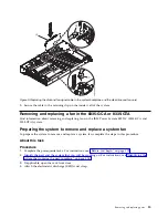
Replace the top and side screws for the power switch See Figure 26.
6.
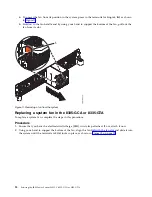
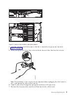
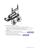
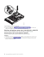
Using the labels, plug the front USB cable (A) and the power switch cable (B) to the system
backplane. See Figure 27 on page 29. Ensure that the cable latch clip snaps into place on the
connectors.
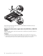
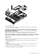
Figure 25. Replacing the front USB cable into the system backplane
Figure 26. Replace the top and side screws
28
Servicing the IBM Power System S822LC (8335-GCA or 8335-GTA)
Содержание S822LC
Страница 1: ...Power Systems Servicing the IBM Power System S822LC 8335 GCA or 8335 GTA IBM...
Страница 2: ......
Страница 3: ...Power Systems Servicing the IBM Power System S822LC 8335 GCA or 8335 GTA IBM...
Страница 16: ...xiv Servicing the IBM Power System S822LC 8335 GCA or 8335 GTA...
Страница 134: ...118 Servicing the IBM Power System S822LC 8335 GCA or 8335 GTA...
Страница 145: ...Notices 129...
Страница 146: ...IBM Printed in USA...


