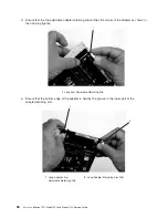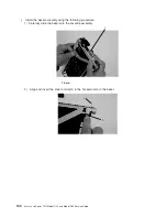
k.
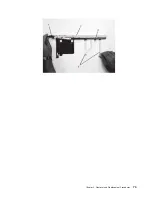
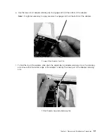
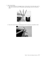
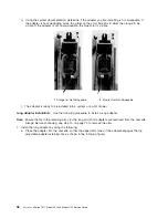
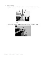
Check
for
the
following:
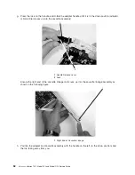
1)
Ensure
that
the
extension
arm
engages
the
pins
on
the
cassette.
You
should
be
able
to
see
the
three
pins
in
the
holes
in
the
arm.
The
bezel
tab
should
be
seated
as
shown
in
the
following
figure.
1
1
1
1
Pin
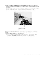
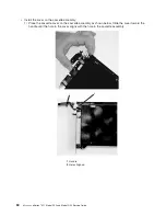
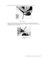
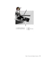
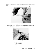
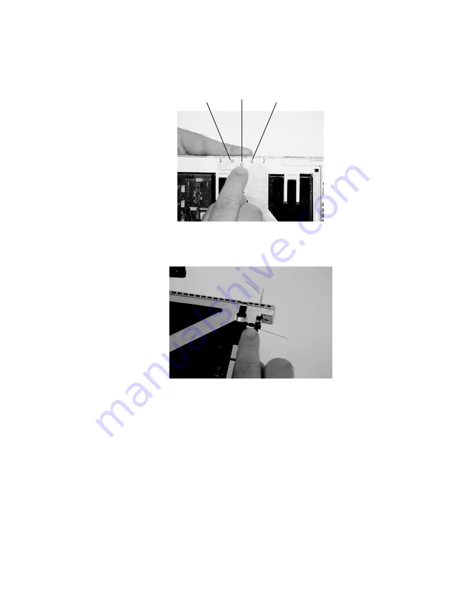
2)
Ensure
the
cover
arm
latch
is
completely
pressed
into
the
hooked
slot
on
the
bezel
as
shown.
1
2
Chapter
3.
Removal
and
Replacement
Procedures
87
Содержание eserver pSeries 7311 D10
Страница 1: ...pSeries 7311 Model D10 and Model D20 Service Guide SA38 0627 01 ERserver...
Страница 2: ......
Страница 3: ...pSeries 7311 Model D10 and Model D20 Service Guide SA38 0627 01 ERserver...
Страница 8: ...vi Eserver pSeries 7311 Model D10 and Model D20 Service Guide...
Страница 12: ...x Eserver pSeries 7311 Model D10 and Model D20 Service Guide...
Страница 14: ...xii Eserver pSeries 7311 Model D10 and Model D20 Service Guide...
Страница 25: ...1 Processor Subsystem 2 I O Subsystem Chapter 1 Reference Information 9...
Страница 89: ...Chapter 3 Removal and Replacement Procedures 73...
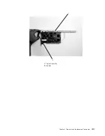
Страница 99: ...2 1 1 Top of Cassette 2 Handle Chapter 3 Removal and Replacement Procedures 83...
Страница 179: ...D10 I O Subsystem Parts continued 1 2 3 4 5 6 7 Chapter 4 Parts Information 163...
Страница 207: ......
Страница 208: ...Printed in USA May 2003 SA38 0627 01...

