Chapter
3.
Removal
and
Replacement
Procedures
Before
performing
any
of
the
removal
or
replacement
procedures
in
this
chapter,
read
the
following
danger
and
caution
notices.
Safety
Considerations
Observe
the
following
safety
precautions
anytime
you
work
with
these
I/O
subsystems.
For
the
I/O
subsystem
you
are
about
to
setup
or
service:
v
The
ac
power
interface
connector
is
considered
the
main
power
disconnect
device.
v
The
I/O
subsystems
have
independent
redundant
power
supply
capabilities,
meaning
that
each
unit
might
be
configured
to
have
two
power
supplies
running
simultaneously
in
the
same
I/O
subsystem.
When
instructed
to
disconnect
the
power
source,
ensure
that
all
power
cables
that
run
to
each
serviced
subsystem
are
disconnected
from
the
power
distribution
bus.
DANGER
An
electrical
outlet
that
is
not
correctly
wired
could
place
hazardous
voltage
on
metal
parts
of
the
system
or
the
devices
that
attach
to
the
system.
It
is
the
responsibility
of
the
customer
to
ensure
that
the
outlet
is
correctly
wired
and
grounded
to
prevent
an
electrical
shock.
Before
installing
or
removing
signal
cables,
ensure
that
the
power
cables
for
the
system
unit
and
all
attached
devices
are
unplugged.
When
adding
or
removing
any
additional
devices
to
or
from
the
system,
ensure
that
the
power
cables
for
those
devices
are
unplugged
before
the
signal
cables
are
connected.
If
possible,
disconnect
all
power
cables
from
the
existing
system
before
you
add
a
device.
Use
one
hand,
when
possible,
to
connect
or
disconnect
signal
cables
to
prevent
a
possible
shock
from
touching
two
surfaces
with
different
electrical
potentials.
During
an
electrical
storm,
do
not
connect
cables
for
display
stations,
printers,
telephones,
or
station
protectors
for
communications
lines.
D05
CAUTION:
This
product
is
equipped
with
a
three-wire
power
cable
and
plug
for
the
user’s
safety.
Use
this
power
cable
with
a
properly
grounded
electrical
outlet
to
avoid
electrical
shock.
C01
CAUTION:
This
unit
has
more
than
one
power
supply
cord.
To
reduce
the
risk
of
electrical
shock,
disconnect
two
power
supply
cords
before
servicing.
C21
41
Содержание eserver pSeries 7311 D10
Страница 1: ...pSeries 7311 Model D10 and Model D20 Service Guide SA38 0627 01 ERserver...
Страница 2: ......
Страница 3: ...pSeries 7311 Model D10 and Model D20 Service Guide SA38 0627 01 ERserver...
Страница 8: ...vi Eserver pSeries 7311 Model D10 and Model D20 Service Guide...
Страница 12: ...x Eserver pSeries 7311 Model D10 and Model D20 Service Guide...
Страница 14: ...xii Eserver pSeries 7311 Model D10 and Model D20 Service Guide...
Страница 25: ...1 Processor Subsystem 2 I O Subsystem Chapter 1 Reference Information 9...
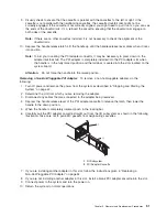
Страница 89: ...Chapter 3 Removal and Replacement Procedures 73...
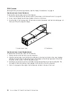
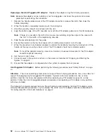
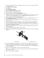
Страница 99: ...2 1 1 Top of Cassette 2 Handle Chapter 3 Removal and Replacement Procedures 83...
Страница 179: ...D10 I O Subsystem Parts continued 1 2 3 4 5 6 7 Chapter 4 Parts Information 163...
Страница 207: ......
Страница 208: ...Printed in USA May 2003 SA38 0627 01...

