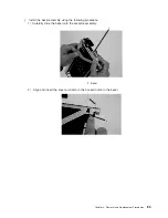
2.
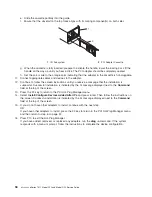
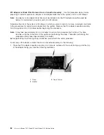
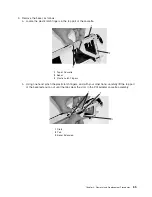
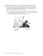
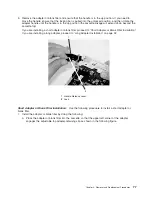
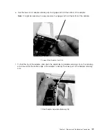
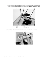
Remove
the
adapter
or
blank
filler
from
the
cassette
linkage
assembly
by
rotating
the
bottom
of
the
tailstock
out,
as
shown
in
the
following
illustration.
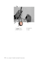
Store
the
adapter
or
blank
filler
in
a
safe
place.
1
Cassette
Linkage
Assembly
3
Handle
2
Bottom
of
Tailstock
3.
The
removal
procedure
for
the
PCI
adapter
cassette
assembly
is
complete.
To
install
a
new
adapter
or
blank
filler
in
the
cassette,
go
to
“Installing
a
Hot-Pluggable
PCI
Adapter”
on
page
57.
Chapter
3.
Removal
and
Replacement
Procedures
71
Содержание eserver pSeries 7311 D10
Страница 1: ...pSeries 7311 Model D10 and Model D20 Service Guide SA38 0627 01 ERserver...
Страница 2: ......
Страница 3: ...pSeries 7311 Model D10 and Model D20 Service Guide SA38 0627 01 ERserver...
Страница 8: ...vi Eserver pSeries 7311 Model D10 and Model D20 Service Guide...
Страница 12: ...x Eserver pSeries 7311 Model D10 and Model D20 Service Guide...
Страница 14: ...xii Eserver pSeries 7311 Model D10 and Model D20 Service Guide...
Страница 25: ...1 Processor Subsystem 2 I O Subsystem Chapter 1 Reference Information 9...
Страница 89: ...Chapter 3 Removal and Replacement Procedures 73...
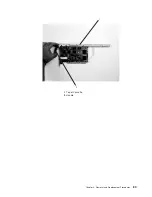
Страница 99: ...2 1 1 Top of Cassette 2 Handle Chapter 3 Removal and Replacement Procedures 83...
Страница 179: ...D10 I O Subsystem Parts continued 1 2 3 4 5 6 7 Chapter 4 Parts Information 163...
Страница 207: ......
Страница 208: ...Printed in USA May 2003 SA38 0627 01...

