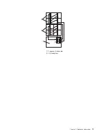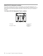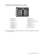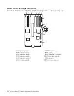
D10
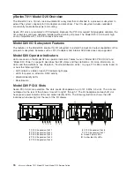
Power
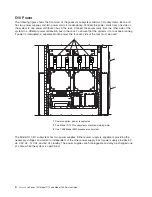
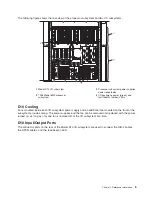
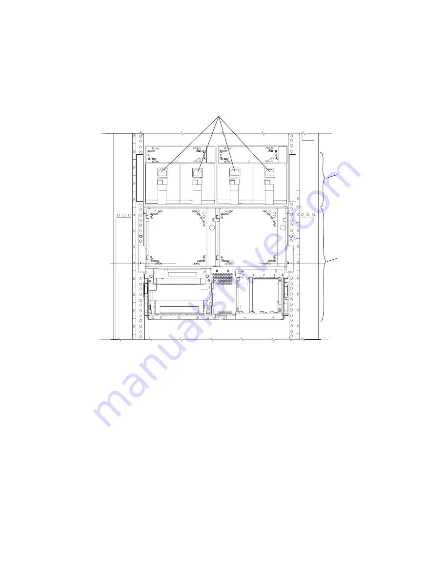
The
following
figure
shows
the
front
view
of
the
pocessor
subsystem
and
two
I/O
subsystems.
Each
unit
has
two
power
supplies
and
two
power
cords
for
redundancy.
Connect
the
power
cords
from
one
side
of
the
system
to
one
power
distribution
bus
in
the
rack.
Connect
the
power
cords
from
the
other
side
of
the
system
to
a
different
power
distribution
bus
in
the
rack.
To
ensure
that
the
systems
in
a
rack
keep
running
if
power
is
interrupted,
a
separate
branch
power
line
for
each
side
of
the
rack
must
be
used.
1
1
2
1
3
1
Power
supplies,
power
receptacles
2
Two
Model
D10
I/O
subsystems
mounted
side-by-side.
3
One
7038
Model
6M2
processor
subsystem
The
Model
D10
I/O
subsystem
has
two
power
supplies.
Either
power
supply
is
capable
of
providing
the
necessary
voltages
and
currents,
independent
of
the
other
power
supply.
Each
power
supply
provides
5V
dc,
3.3V
dc,
-12V
dc,
and
5V
dc
standby.
The
power
supplies
are
hot-pluggable
and
may
be
changed
one
at
a
time
while
the
system
is
operational.
4
Eserver
pSeries
7311
Model
D10
and
Model
D20
Service
Guide
Содержание eserver pSeries 7311 D10
Страница 1: ...pSeries 7311 Model D10 and Model D20 Service Guide SA38 0627 01 ERserver...
Страница 2: ......
Страница 3: ...pSeries 7311 Model D10 and Model D20 Service Guide SA38 0627 01 ERserver...
Страница 8: ...vi Eserver pSeries 7311 Model D10 and Model D20 Service Guide...
Страница 12: ...x Eserver pSeries 7311 Model D10 and Model D20 Service Guide...
Страница 14: ...xii Eserver pSeries 7311 Model D10 and Model D20 Service Guide...
Страница 25: ...1 Processor Subsystem 2 I O Subsystem Chapter 1 Reference Information 9...
Страница 89: ...Chapter 3 Removal and Replacement Procedures 73...
Страница 99: ...2 1 1 Top of Cassette 2 Handle Chapter 3 Removal and Replacement Procedures 83...
Страница 179: ...D10 I O Subsystem Parts continued 1 2 3 4 5 6 7 Chapter 4 Parts Information 163...
Страница 207: ......
Страница 208: ...Printed in USA May 2003 SA38 0627 01...

