Maintenance
Analysis
Procedures
(MAPs)
The
maintenance
analysis
procedures
(MAPs)
provide
the
service
representative
a
step-by-step
procedure
to
analyze
a
problem
with
the
system
and
I/O
subsystem
hardware.
Be
prepared
to
record
code
numbers
and
other
data
while
using
the
MAPs.
Because
the
Model
D10
and
Model
D20
are
subsystems,
refer
to
your
system’s
service
guide.
The
system’s
service
guide
contains
all
of
the
MAPs
needed
for
servicing
the
Model
D10
and
Model
D20
I/O
subsystems.
Checkpoints
Checkpoints
display
on
the
system
operator
panel
and
the
virtual
terminal
while
the
system
unit
is
powering
on
and
going
through
the
initial
program
load
(IPL).
See
the
system’s
service
guide
for
descriptive
information
and
a
complete
listing
of
all
checkpoints
used
by
the
Model
D10
and
Model
D20
I/O
subsystems.
Error
Code
to
FRU
Index
The
Error
Code
to
FRU
Index
lists
fault
symptoms
and
possible
causes.
The
most
likely
cause
is
listed
first.
Use
this
index
to
help
you
decide
which
FRUs
to
replace
when
servicing
the
Model
D10
or
Model
D20
I/O
subsystem.
See
your
system’s
service
guide
for
more
information
and
a
complete
listing
of
all
error
codes
and
FRUs
used
by
the
Model
D10
and
Model
D20
I/O
subsystem.
Using
the
Service
Processor
The
service
processor
is
in
the
processor
subsystem
to
which
your
I/O
subsystem
is
connected
and
runs
on
its
own
power
boundary.
The
service
processor
continually
monitors
hardware
attributes
and
the
environmental
conditions
within
the
system
and
connected
I/O
subsystems.
The
service
processor
is
controlled
by
firmware
and
does
not
require
the
operating
system
to
be
operational
to
perform
its
tasks.
The
service
processor
menus
allow
you
to
configure
service
processor
options,
as
well
as
enable
and
disable
functions.
Service
processor
menus
are
available
using
an
ASCII
terminal
or
an
HMC
virtual
terminal
window
when
OK
is
displayed
on
the
operator
panel
or
when
the
service
processor
has
detected
a
system
problem
(such
as
a
surveillance
failure).
For
more
information
about
the
service
processor
for
the
system
to
which
your
I/O
subsystem
is
connected,
see
the
system’s
service
guide.
Using
System
Management
Services
Use
the
system
management
services
menus
to
view
information
about
the
processor
subsystem
to
which
the
I/O
subsystem
is
connected.
For
more
information
about
the
service
processor,
see
the
service
guide
for
the
attached
system.
40
Eserver
pSeries
7311
Model
D10
and
Model
D20
Service
Guide
Содержание eserver pSeries 7311 D10
Страница 1: ...pSeries 7311 Model D10 and Model D20 Service Guide SA38 0627 01 ERserver...
Страница 2: ......
Страница 3: ...pSeries 7311 Model D10 and Model D20 Service Guide SA38 0627 01 ERserver...
Страница 8: ...vi Eserver pSeries 7311 Model D10 and Model D20 Service Guide...
Страница 12: ...x Eserver pSeries 7311 Model D10 and Model D20 Service Guide...
Страница 14: ...xii Eserver pSeries 7311 Model D10 and Model D20 Service Guide...
Страница 25: ...1 Processor Subsystem 2 I O Subsystem Chapter 1 Reference Information 9...
Страница 89: ...Chapter 3 Removal and Replacement Procedures 73...
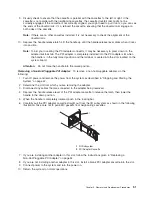
Страница 99: ...2 1 1 Top of Cassette 2 Handle Chapter 3 Removal and Replacement Procedures 83...
Страница 179: ...D10 I O Subsystem Parts continued 1 2 3 4 5 6 7 Chapter 4 Parts Information 163...
Страница 207: ......
Страница 208: ...Printed in USA May 2003 SA38 0627 01...

